Mould for forming optical elements and the optical elements

A technology of optical components and molds, which is applied in the field of optical components, can solve the problems of increased roughness of the forming surface, uneven crystal growth, etc., and achieve the effect of preventing welding

Active Publication Date: 2004-09-01
OLYMPUS CORP
View PDF0 Cites 5 Cited by
  • Summary
  • Abstract
  • Description
  • Claims
  • Application Information

AI Technical Summary

Problems solved by technology

[0011] The inventors of the present invention have found from the above two points that the crystal growth and oxidation speed of each base material grain and the degree of progress have different effects on each crystal of the noble metal layer. Since the crystal growth and oxidation speed of each crystal of the noble metal layer, Depending on the degree of progress, non-uniform crystal growth, etc. will occur, and the roughness of the molding surface will increase.

Method used


Image

  • Mould for forming optical elements and the optical elements

Examples


Embodiment Construction

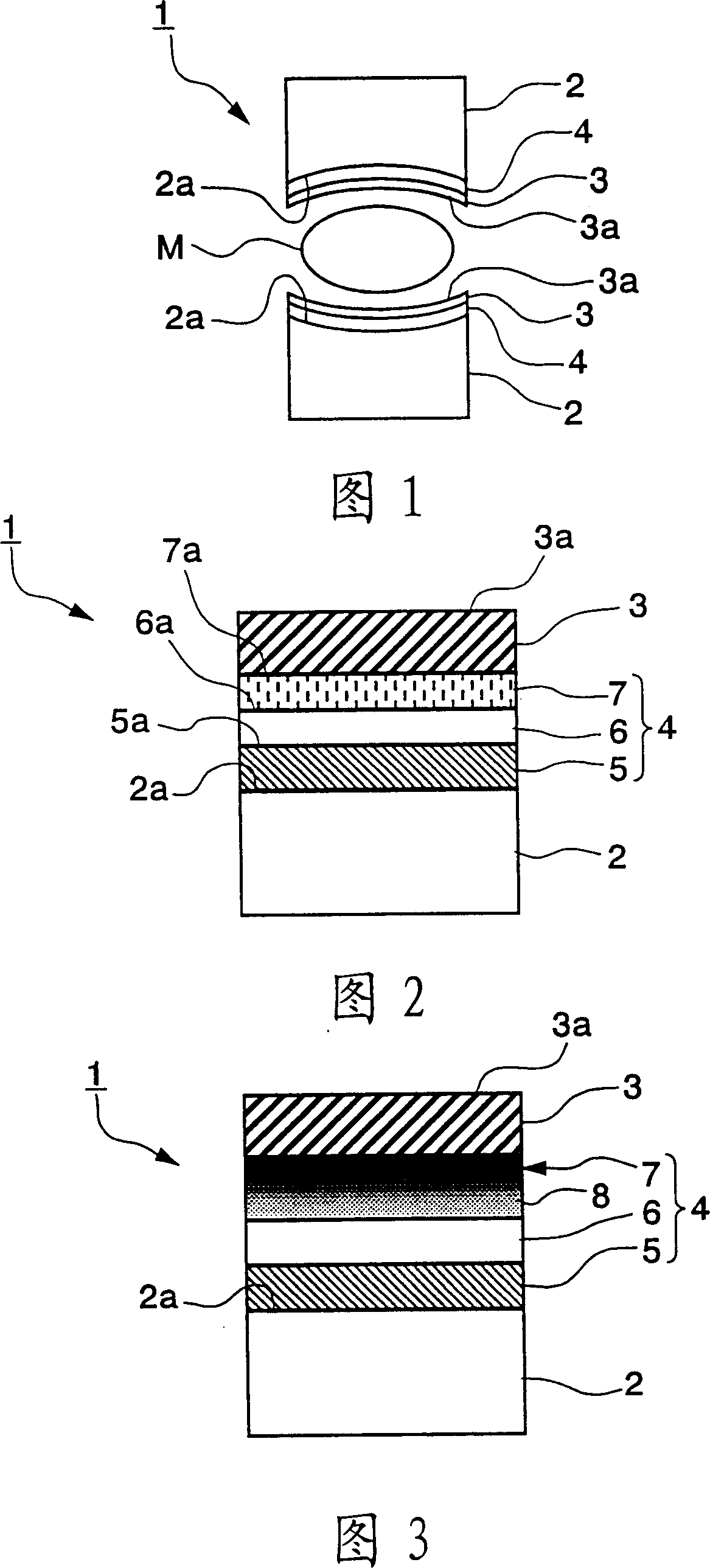
[0037] 1, 2 show a first embodiment of the present invention. The mold for forming an optical element in this embodiment is a mold for producing a convex lens (optical element) by press molding. As shown in FIG. 1, the mold 1 for forming such an optical element has the following parts: a pair of mold base materials 2, 2; formed on the surface 2a of each mold base material 2, with The surface layer 3 of the molding surface 3 a which the glass raw material M contacts; and the intermediate layer 4 formed between the two mold base materials 2 and the surface layer 3 .

[0038] The mold base material 2 is made of sintered cemented carbide or silicon carbide, and its surface 2a is made into a concave shape matching the curvature radius of the convex lens.

[0039] As shown in FIG. 2 , the intermediate layer 4 is composed of a base material surface layer 5 , a metal layer 6 and a nitride layer 7 . The base material surface layer 5 is in contact with the surface 2 a of the mold base...


PUM

PropertyMeasurementUnit
diameteraaaaaaaaaa

Abstract

The die is comprised of a die base material consisting of a sintered hard alloy or silicon carbide, a surface layer formed on the surface of the die base material and brought into contact with a glass material in press molding, and an intermediate layer formed between the die base material and the surface layer. The surface layer is formed from at least one element selected from among platinum, palladium, iridium, osmium, ruthenium, and rhenium or an alloy or compound containing these elements. The intermediate layer has a surface base material layer which consists of at least a substance selected from among tungsten, carbon, tungsten carbide, and silicon carbide, is in an amorphous state or in a crystalline state with a crystal grain diameter smaller than that of the substance constituting the die base material, and is brought into contact with the surface of the die base material.

Description

technical field [0001] The present invention relates to an optical element molding die for producing optical elements such as lenses and prisms by press-molding glass raw materials, and the optical elements formed therefrom. Background technique [0002] In recent years, as a method of manufacturing optical elements from such a glass raw material, there is a press molding method using a molding die. With this manufacturing method, there is an advantage that the optical element can be manufactured simply and inexpensively because grinding processing is not required. In the past, various researches have been carried out on this kind of mold for forming optical elements for stamping, so that the forming surface that contacts the glass raw material during the forming process can maintain the surface roughness, so that it can be used for a long time. in the shaping of optical components. [0003] That is, such a mold for molding an optical element has a mold base material, a no...

Claims


Application Information

Patent Timeline
Patent Type & Authority Applications(China)
IPC IPC(8): C03B11/06
CPCC03B2215/32C03B2215/17C03B2215/31C03B2215/34C03B2215/11C03B2215/12C03B2215/16C03B11/086
Inventor 葛西广明
Owner OLYMPUS CORP
Why Eureka
Try Eureka