Differential confocal scanning detection method with high spatial resolution

A high spatial resolution, differential confocal technology, applied in measuring devices, instruments, optical devices, etc., can solve the problem that the effect of three-dimensional super-resolution is not obvious, and achieve the effect of improving lateral resolution and axial resolution

Inactive Publication Date: 2004-09-08
HARBIN INST OF TECH
View PDF3 Cites 118 Cited by
  • Summary
  • Abstract
  • Description
  • Claims
  • Application Information

AI Technical Summary

Problems solved by technology

[0018] However, the above-mentioned three-dimensional pupil filter requires both lateral super-resoluti

Method used


Image

  • Differential confocal scanning detection method with high spatial resolution
  • Differential confocal scanning detection method with high spatial resolution
  • Differential confocal scanning detection method with high spatial resolution

Examples


Embodiment Construction

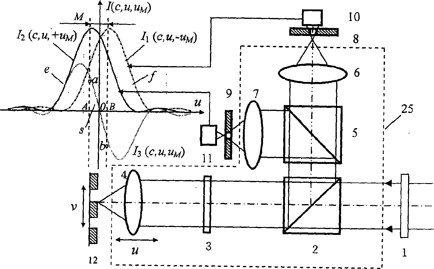
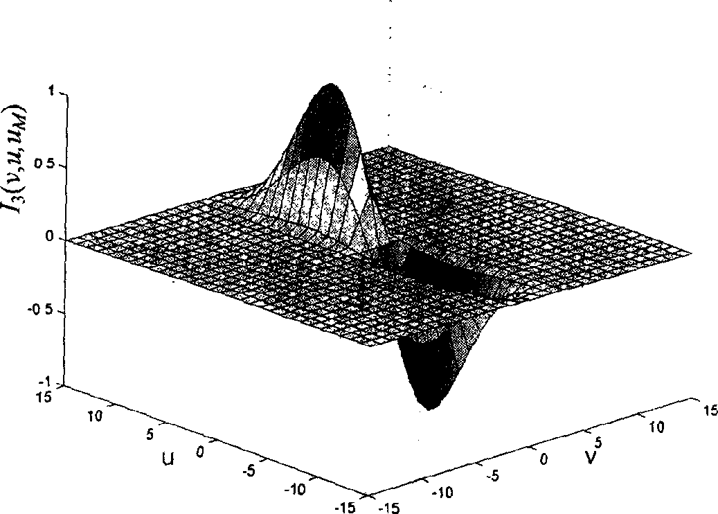
[0065] Such as figure 2 As shown, the dotted frame part is a differential confocal microscope dual receiving optical path arrangement 25, after the incident light beam is transmitted through the pupil filter 1, the polarizing beam splitter 2, and the quarter wave plate 3, the measured objective lens 4 is focused on the measured sample 12 surfaces. The measuring light reflected by the surface of the tested sample 12 is reflected by the polarizing beam splitter (PBS) 2 through the quarter-wave plate 3 again, and then divided into two beams of light by the beam splitter (BS) 5, and are respectively separated by two identical beam splitters. Condensers 6 and 7 focus. The pinhole 8 and the detector 10 are placed at the back-focus distance C of the focal plane of the condenser 6, and the pinhole 9 and the detector 11 are placed at the front-focus distance D of the focal plane of the condenser 7, and the sizes of C and D are both M, and the distance The optical normalized displace...


PUM


Abstract

The present invention belongs to the field of fine surface structure measuring technology, and relates to one kind of differential confocal scanning detection method with high spatial resolution. Differential confocal microscopic double receiving light path configuration and double detector subtraction form the differential confocal signal in measuring the workpiece. Optical super-resolution confocal microscopic detection method is adopted to raise the transverse resolution, and differential confocal microscopic detection method is adopted to raise the longitudinal resolution, so as to reach differential confocal scanning detection of high spatial resolution. The method can meet the requirements in high spatial resolution, high precision and great measurement range, and is especially suitable for the measurement of fine surface 3D structure, miniature steps, miniature grooves, line width, surface appearance, etc.

Description

technical field [0001] The invention belongs to the technical field of microscopic detection, and in particular provides a method for detecting surface three-dimensional microstructures, microsteps, microstructure grooves, line widths of integrated circuits and surface topography. Background technique: [0002] With the development of semiconductor technology to VLSI, millimeter wave and quantum devices, microfabrication technology has entered the field of deep submicron and nanometer three-dimensional processing technology, so it is urgent to study large-scale, high-space (ie, axial and lateral) resolution imaging and detection technologies. [0003] In the field of detection with high spatial resolution, non-contact scanning probe detection methods will undoubtedly play a leading role. In recent years, despite the rapid development of scanning probe detection methods based on the principles of scanning tunneling, atomic force, and near-field optics, the spatial resolution...

Claims


Application Information

Patent Timeline
IPC IPC(8): G01B11/24G01B11/30
Inventor 赵维谦谭久彬邱丽荣
Owner HARBIN INST OF TECH
Why Eureka
Try Eureka