Deep sand filter

A sand filter and depth-type technology, which is applied in the direction of gravity filter, loose filter material filter, filter separation, etc., can solve the problems of energy input and cost increase, operation efficiency decrease, environmental pollution increase, etc., and achieve simple structure, The effect of small equipment investment and increased filtration area

Inactive Publication Date: 2004-09-15
安逢龙
View PDF1 Cites 7 Cited by
  • Summary
  • Abstract
  • Description
  • Claims
  • Application Information

AI Technical Summary

Problems solved by technology

[0003] The existing sand filter equipment has the following defects: 1. It belongs to the surface filter, that is, the filtration accuracy is mainly achieved by the size of the surface gap of the sand.
2. It is easy to be fouled and needs frequent backwashing to regenerate its filtration function
Because their utilization rate is relatively low, resulting in a huge waste of resources
3. The frequency of backwashing is high, which means that the normal operation time is short, and the operating efficiency is reduced. It also means that the utilization rate of water is reduced and the pollution environment caused by backwashing is increased.
4. Normal filtration and backwashing devices need to be installed in the same filter device, and equipment such as water distribution or air distribution must also be configured, which has a complex structure and high cost
5. Pumps and other power devices are required, and the consumption of power such as electricity means energy input and cost increases. It is not suitable or even impossible to use in general fields or areas where power distribution has not yet been achieved or where power costs are relatively high.
6. The requirements for equipment materials are relatively high, generally need to have anti-corrosion properties, such as stainless steel or carbon steel, etc., the cost is quite high
However, surface filtration generally has a small dirt-holding capacity and requires frequent flushing or backwashing to regenerate
Depth filtration generally has the advantages of large dirt-holding capacity, small filtration pressure difference, and long single service life, but it is generally not easy to regenerate or the effect of regeneration is not very good

Method used


Image

  • Deep sand filter
  • Deep sand filter

Examples


Embodiment 1

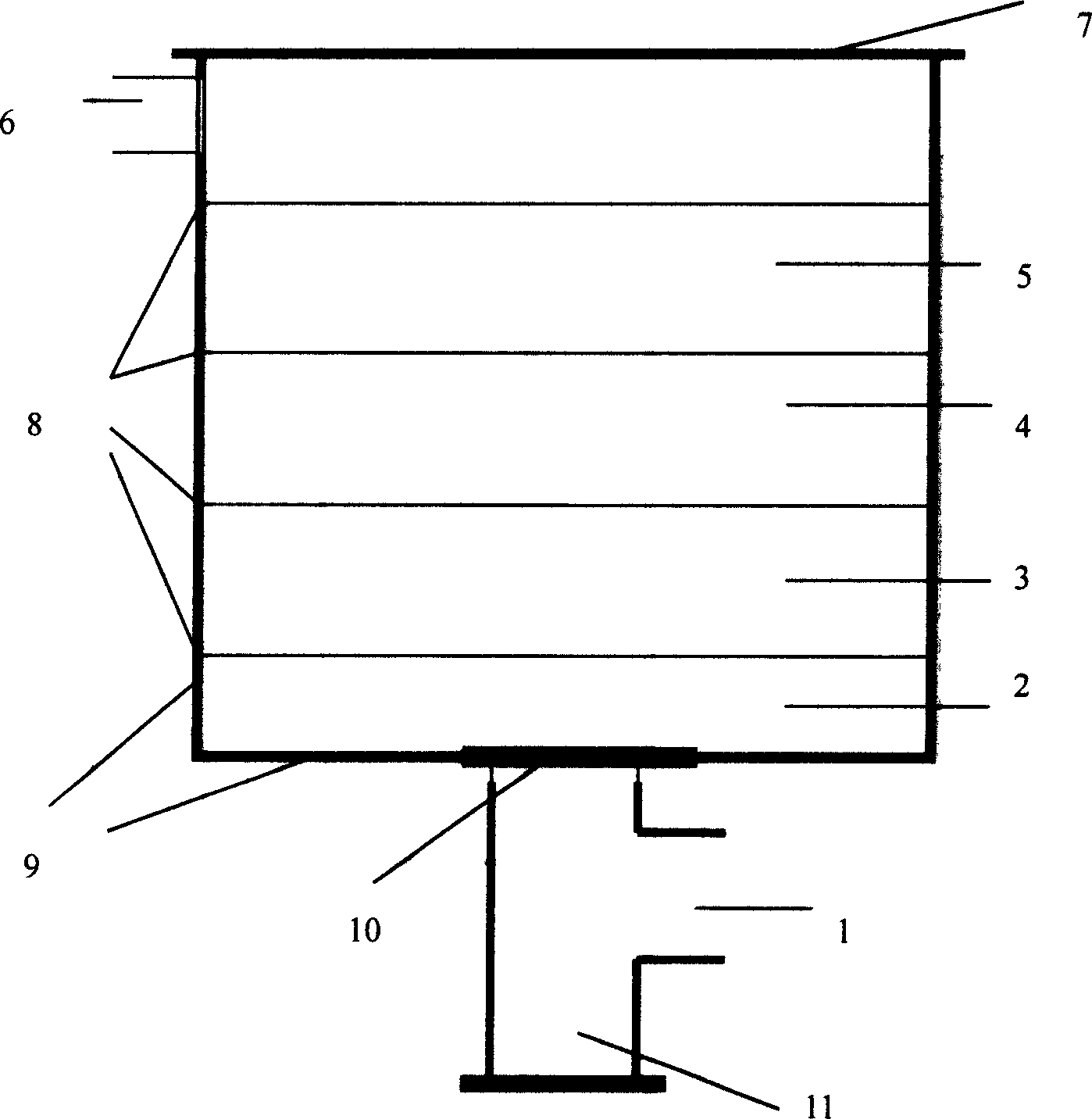
[0051] A cylindrical upflow depth type sand filter made of ABS material, such as figure 1 Shown, body of wall 9 wall thicknesses 3 millimeters, internal diameter 200 millimeters, height 500 millimeters, water inlet pipe 1 and outlet pipe 6 internal diameters 30 millimeters, top is provided with seal cover 7. There are three layers of sand inside, and a partition 8 is arranged between each layer of sand. The coarse sand area 3 in the bottom layer has a grain size of 20-2 mm and a thickness of 100 mm. The sand grain size of the middle sand area 4 in the middle layer is 2-0.3 mm. , thickness 50, the sand particle size of the upper fine sand area 5 is 0.3-0.01 mm, and the thickness is 200 mm. There is a 100mm height difference between the upper part of the sand layer and the outlet pipe to prevent the fine sand from flowing out together with the filtered water. Take 300 liters of rainwater flowing down from the roof, suspended matter SS 150ppm, sludge index SDI 30, and filter it ...

Embodiment 2

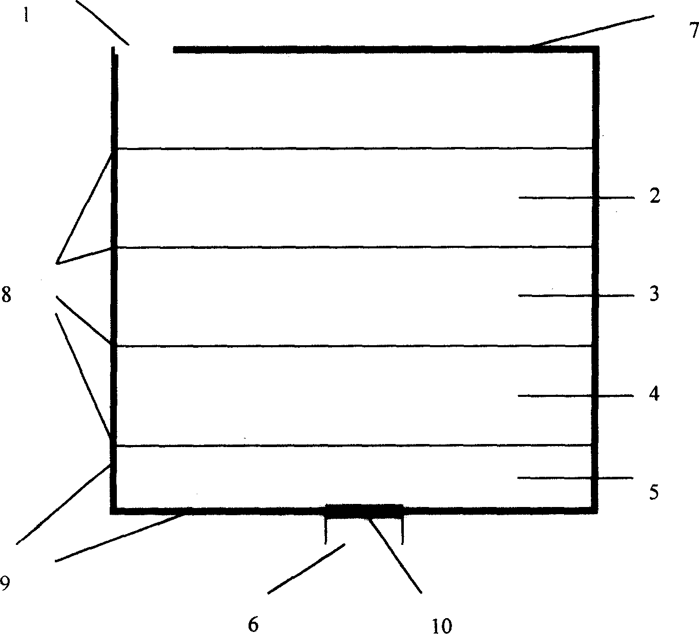
[0053] Square column type downflow depth type sand filter, such as figure 2 As shown, the wall body 9 and the water outlet pipe 6 are made of glass, the wall thickness is 1 mm, the upper cover 7 is arranged on it, the side length is 10 mm, and the height is 35 mm. There are three layers of sand inside, and the size of the upper layer 2 sand grains is 2-0.3 mm. , 5 mm thick, the middle layer 3 sand grain size is 0.3-0.1 mm, 5 mm thick, the lower layer 4 sand grain size is 0.1-0.01 mm, 15 mm thick, the bottom, middle and upper parts use apertures of 0.01 mm, 0.01 mm, 0.1 mm And 0.3 mm of 1 mm thick polyester sheet separator 8 with a porosity of 20%. Collect 200ml of clean rainwater flowing down from the roof, suspended solids SS100ppm, sludge index SDI 20, rainwater enters the deep sand filter from inlet 1, and as the rainwater flows down from the bottom, large suspended solids are mainly trapped in the upper layer of large and medium sand particles , fine suspended solids are...

Embodiment 3

[0055] Next to a highway, there is a water injection well with an inner diameter of 200 mm and a depth of 10 meters. In order to effectively utilize rainwater resources, configure the rectangular cylindrical upflow type depth sand filter of the present invention to the water injection well, which is 4 meters long, 2 meters wide and 1 meter high, because the rainwater surface below cannot reach the top of the depth sand filter. Therefore, only cover the upper part of the filter with a soft plastic cloth to prevent rainwater and dust from entering the water injection well without being filtered by the deep sand filter without sealing. There is a height difference of 1 meter between the upper parts of the filters for faster filtration. There are 5 layers of sand inside the filter, the particle size and thickness are different from bottom to top, the first layer is 200-20 mm, 400 mm, the second layer is 20-2 mm, 200 mm, the third layer is 2-0.6 mm, 150 mm, the fourth layer, 0.6-0...


PUM

PropertyMeasurementUnit
thicknessaaaaaaaaaa
thicknessaaaaaaaaaa
depthaaaaaaaaaa

Abstract

The invention is a depth-type sand filter, the size of sand gradually diminishing with the flow direction of the normal filtering fluid. It leads the fluid to the inlet of the sand filter through the pipeline, firstly holds back big suspension through big sand area, then holds back medium suspension through medium sand area, finally eliminates most fine suspension through fine sand area, and then makes the fluid flow out from the outlet. It is composed of wall body, filtering sand and ground leak; the wall body is set with inlet and outlet, the ground leak is set under the wall body, the filtering sand is spread in the liquid flow direction in turn according to the size. It can adopt upflow and downflow modes. It can stably and economically run in a wide range. It is applied to economical sand filtering field, especially the field where the sand filter is used infrequently or discontinuously.

Description

technical field [0001] The invention belongs to a water filtering device, in particular to a deep type sand filter. Background technique [0002] Sand filters are simple and economical filters because the filter media is sand, which is cheap and readily available. Existing sand filters mainly include coarse sand filters and fine sand filters. The basic structure is that there are fine stones and larger stones on the bottom, and sand or fine sand on the top. The stone structure below is mainly designed for the convenience of collecting filtered water and backwashing. The coarse sand or fine sand above mainly plays a filtering role. The filtration accuracy of the sand filter is mainly achieved by the gap size of the coarse sand or fine sand. The normal flow direction of the filtered fluid of the existing sand filter is from top to bottom, and when the system is fouled to a certain extent or the filter pressure difference reaches a specified va...

Claims


Application Information

Patent Timeline
Patent Type & Authority Applications(China)
IPC IPC(8): B01D24/22
Inventor 安逢龙
Owner 安逢龙
Why Eureka
Try Eureka