
Nanometer magnetic sensitive speed sensor

A speed sensor and nano-magnetic technology, applied in the field of automobile wheel speed sensing and detection, can solve the problems of poor sensor temperature stability, leakage signal, open magnetic circuit, etc.

Inactive Publication Date: 2004-10-20
EAST CHINA NORMAL UNIVERSITY
View PDF0 Cites 8 Cited by
  • Summary
  • Abstract
  • Description
  • Claims
  • Application Information

AI Technical Summary

Problems solved by technology

[0003] The disadvantage of the electromagnetic induction speed sensor is that when the wheel speed is too low, the magnetic flux changes very slowly, the output signal is too small, and it is easy to cause signal leakage
In addition, the detection distance of this type of sensor, that is, the gap between the sensor head and the gear rim is only allowed to be 0.5 ~ 1mm
[0004] The disadvantage of the Hall speed sensor is low sensitivity and small output signal. Even after amplification, the detection distance is only 0.2 ~ 0.5mm. In addition, this type of sensor has poor temperature stability and must be temperature compensated.
[0005] The disadvantage of the magnetoresistive speed sensor is that the sensitivity of the sensor is not high, the magnetic circuit is open, and the anti-electromagnetic interference performance is poor.

Method used


Image

  • Nanometer magnetic sensitive speed sensor
  • Nanometer magnetic sensitive speed sensor
  • Nanometer magnetic sensitive speed sensor

Examples


Embodiment

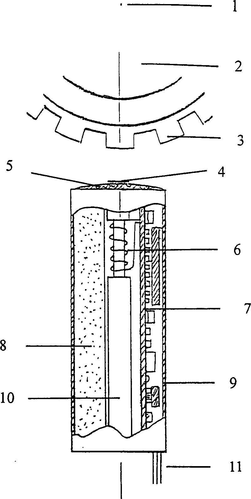
[0016] The magnetic head adopts φ2×2mm cylindrical permanent magnet.

[0017] The adjustable bias magnet adopts permanent magnet ferrite with φ4×6mm band.

[0018] The coil tube of the coil 6 is a φ2.5×12mm sealed ceramic tube with covers at both ends, and the coil 6 uses a φ0.04mm high-performance enameled wire, which is wound 120 turns outside the above-mentioned ceramic tube.

[0019] The iron-based nano-magnetic strip 13 is made of iron-based nano-microcrystalline FeCuNbSiB material, with a size of 12×1×0.025 mm.

[0020] The magnetically permeable core 14 is an iron core made of soft iron, and its size is φ1×8mm.

[0021] The shell 9 is a ferromagnetic shell made of soft iron.

[0022] The skeleton 8 is a special-shaped member made of polytetrafluoroethylene.

[0023] The seal 5 is a cover made of epoxy, which plays a role of fixing and protecting between the magnetic head 4 , the frame 8 and the shell 9 .

[0024] The block diagram of the circuit structure of the pos...


PUM


Abstract

A nano-type magnetosensitive rotation speed sensor is composed of sensing unit and post-processing circuit. Said sensing unit consists of magnetic head, Fe-base nano magnetic band wound by coil L, adjustable bias magnet and casing. Said post-processing circuit comprises voltage stabilizer, magnetosensitive oscillator, filter amplifier, shaper and OC gate. Its advantages are high sensitivity, long active distance, high thermal stability and anti-interference power, and long service life.

Description

technical field [0001] The invention relates to a nano-magnetic sensitive rotational speed sensor, which belongs to the technical field of wheel machine equipment and motors, especially the rotational speed sensing and detection of automobile wheels. Background technique [0002] The ideal condition of automobile braking is that the slip rate of the wheel is maintained between 8% and 35%, so that the wheel brakes without locking and obtains the maximum ground braking force and large longitudinal and lateral adhesion coefficients. The brake system that makes the car brake under the above ideal conditions usually consists of a speed sensor control unit and a hydraulic unit. Most of the speed sensors in the background art are electromagnetic induction, Hall and magnetoresistance speed sensors, which are installed near the rim of the gear that rotates with the wheel to detect the speed of the wheel. But they are deficient to varying degrees. [0003] The d...

Claims


Application Information

Patent Timeline
IPC IPC(8): G01P3/481
Inventor 杨燮龙杨介信戴文恺
Owner EAST CHINA NORMAL UNIVERSITY
Learn More