
Micro dynamic piezoresistance pressure sensor and manufacturing method thereof

A pressure sensor, dynamic piezoresistive technology, applied in the direction of fluid pressure measurement by changing ohmic resistance, to achieve the effect of ensuring dynamic frequency response characteristics

Active Publication Date: 2004-11-10
王文襄
View PDF0 Cites 18 Cited by
  • Summary
  • Abstract
  • Description
  • Claims
  • Application Information

AI Technical Summary

Problems solved by technology

The chip of Kulite's micro sensor has a small radial size, so the natural frequency is high, but due to the need to face the medium, the influence of medium dust and the influence of light effects, Kulite has to package products on the front of the silicon chip A thin cap with an array of holes punched by a laser is placed in front of the front, and it is not only for ventilation but also to prevent dust particles from hitting the center of the thinnest and easily punctured film at high speed. These array holes are usually called M-type or S-shaped cloth is placed on the outer edge of the film, this protection will seriously affect the dynamic frequency response of the use

Method used


Image

  • Micro dynamic piezoresistance pressure sensor and manufacturing method thereof
  • Micro dynamic piezoresistance pressure sensor and manufacturing method thereof
  • Micro dynamic piezoresistance pressure sensor and manufacturing method thereof

Examples


Embodiment Construction

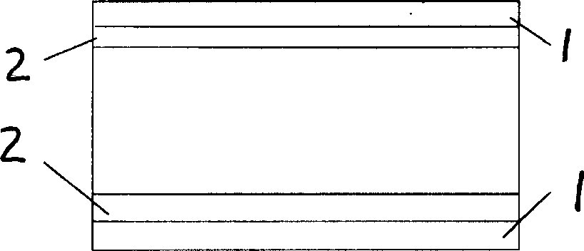
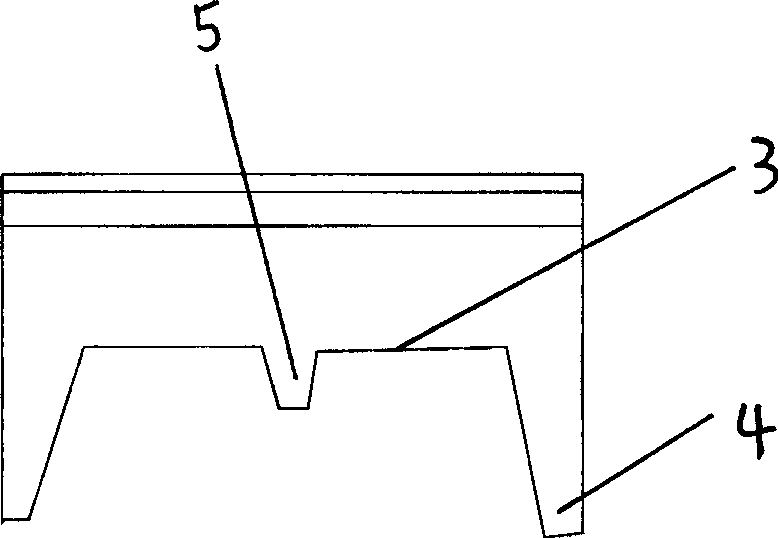
[0052] The micro pressure sensitive chip is manufactured by MEMS silicon micromachining technology. The unit size of the chip is 2.2×2.2mm, the size of the sensitive diaphragm is 1.4×1.4mm, and an island-shaped hard core is left in the center of the diaphragm. The size of the hard core is 0.8×0.8mm, the force-sensitive detection resistor is distributed on the film between the hard core and the boundary hard frame, and the position is determined according to the design method of the E-type sensitive chip. The implementation steps are as follows Figure 1 to Figure 5 The implementation shown:

[0053] figure 1 The double-sided polished silicon wafer used as an elastic element is covered with 1um thick SiO on both sides by traditional thermal oxidation technology in MEMS technology processing. 2 layer, and then use the standard LPCVD method to cover 3000A thick Si on both sides 3 N 4 Floor. figure 2 is to protect the positive Si 3 N 4 layer and SiO 2 Layer, use two photo...


PUM

PropertyMeasurementUnit
Outer diameteraaaaaaaaaa
Thicknessaaaaaaaaaa
Outer diameter φaaaaaaaaaa

Abstract

The invention relates to a micro-type dynamic piezoresistive pressure sensor and its making method, using MEMS silicon bulk micromachining method to make a pressure sensitive chip of E-shaped silicon cup structure, the reverse side of the chip is welded with static seal technique, Pyres glass ring and Hitachi alloy ring, to form silicon back contact medium quasi-level packaging, the reverse back of the chip is covered with anti-interference insulating layer, the right side of the chip is connected with a lead cable through connecting circuit, the sensor tube cap with cable drawing-off mouth at the tail is hermetically welded to the Hitachi alloy ring to form sealed isolation between the side pressure surface and the back pressure cavity, the tail of the tube cap squeezes tightly the cable without sealing, the nozzle part of the sleeve covered on the cable is hermetically covered on the tail of the tube cap, the heat-shrinkable tube segment covered on the cable is hermetically fixed with the outer end part of the sleeve nozzle, thus implementing atmosphere connection between the back pressure cavity and the measured environment, and it is used in shrinkage mould test for hydraulic engineering like dam, ship gate, pier, embankment, etc. and has low measuring range, high sensitivity, strong anti-interference performance, and good dynamic performance during fluid dynamic test.

Description

technical field [0001] The invention relates to a miniature dynamic piezoresistive pressure sensor and a manufacturing method thereof, in particular to a micro dynamic piezoresistive pressure sensor based on MEMS (Micro Electro Mechanical System) silicon micromachining technology and a manufacturing method thereof, especially for large Hydraulic shrinkage tests of dams, ship locks, bridge piers, dikes, ships, torpedoes and offshore platforms. Background technique [0002] The silicon micromachining technology of MEMS (Micro Electro Mechanical System) technology was used in the manufacture of piezoresistive pressure sensors in the late 1970s. Using the piezoresistive effect of silicon, a certain crystal orientation on the silicon wafer was used by the planar integrated circuit process. , A strain-detecting piezoresistor made at a certain position by oxidation diffusion or ion implantation doping, photolithography, etc., and interconnected to form a Wheats...

Claims


Application Information

Patent Timeline
IPC IPC(8): G01L9/06
Inventor 王文襄李水侠刘秀娥
Owner 王文襄
Learn More