
Preparing method for quadrpyramid microstructure array

A microstructure array and quadrangular pyramid technology are applied in the field of fabrication of quadrangular pyramid microstructure arrays, which can solve the problems that affect the application effect of components and cannot be used to manufacture quadrangular pyramid microstructure arrays, etc. Guarantee the effect of surface shape accuracy and simple process

Inactive Publication Date: 2004-12-08
INST OF OPTICS & ELECTRONICS - CHINESE ACAD OF SCI
View PDF0 Cites 8 Cited by
  • Summary
  • Abstract
  • Description
  • Claims
  • Application Information

AI Technical Summary

Problems solved by technology

Therefore this method can only be used for making the quadrangular pyramid microstructure array of smaller relief depth (the etching depth is the maximum of 4 microns), and cannot be used for making the quadrangular pyramid microstructure array of larger depth, and for some special applications In terms of field, the depth of micro-relief will directly affect the application effect of components

Method used

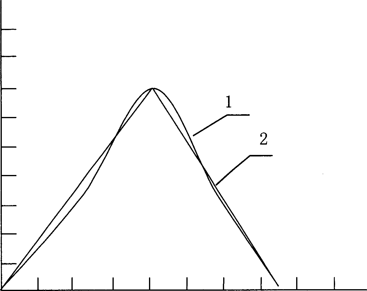
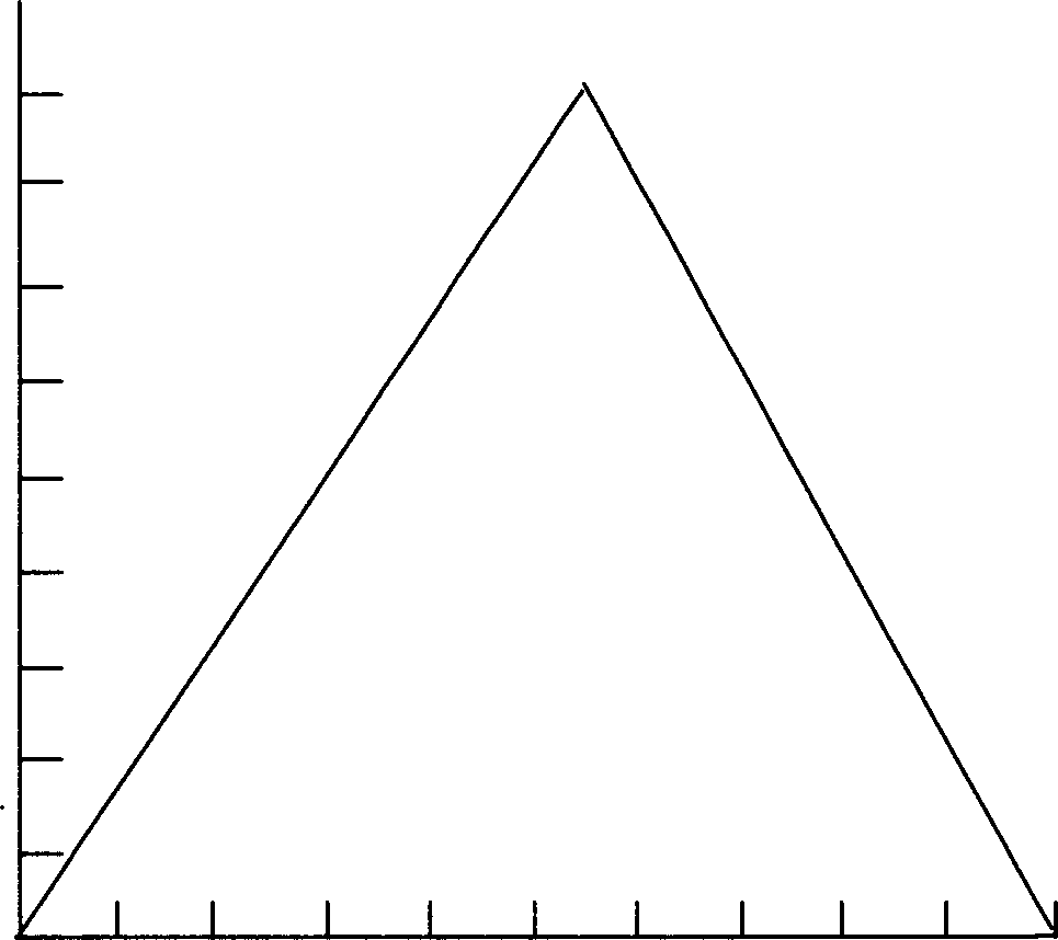
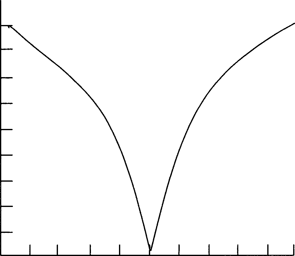

Image

  • Preparing method for quadrpyramid microstructure array
  • Preparing method for quadrpyramid microstructure array
  • Preparing method for quadrpyramid microstructure array

Examples


Embodiment 2

[0038] Example 2, making a small-diameter continuous deep-relief microstructure array with a diameter k=17 μm. Adopt positive photoresist to be photoresist material, etching depth h=5 μm, its fabrication steps are as follows (similar to the step that adopts with embodiment 1):

[0039] (1) According to the etching depth h=5 μm and the etching aperture k=17 μm of the microstructure array relief to be etched, calculate the cross-sectional view f(x) of the microstructure relief;

[0040] (2) According to the micro-relief structure f(x), the mask unit pattern g required for processing the quadrangular pyramid microstructure 0 (x) design;

[0041] (3) Using laser direct writing technology for mask direct writing;

[0042] (4) Using the projection exposure system, project the prepared mask unit on the photoresist for cross-exposure, and move the mask continuously during the exposure process;

[0043] (5) Perform timing development and hardening of the photoresist after continuous...


PUM

PropertyMeasurementUnit
depthaaaaaaaaaa
depthaaaaaaaaaa
depthaaaaaaaaaa

Abstract

The method is as the follows, sectional drawing of terapyramid form microstructure array required to be prepared is calculated out according to required etching depth and etching aperture, exposure distribution required at surface of anticorrosion compound is calculated according to the sectional drawing, mask drawing is designed as per required exposure distribution and the required exposure distribution at anticorrosion compound surface can be obtained by controlling mask moving speed and exposing time as microstructure array is finally built after developing and film hardening.

Description

technical field [0001] The invention relates to a method for manufacturing a microlens array, in particular to a method for manufacturing a quadrangular pyramid microstructure array. Background technique [0002] Due to its special structural characteristics, the quadrangular pyramid microstructure array can be used as a traceable reflective element and a light splitting element, and has very good application prospects in the fields of civil and military scientific research. However, the existing microfabrication method will not only bring serious high-frequency loss, but also cause serious distortion in the low-frequency part of the microstructure. Due to certain defects in the manufactured components, it has been difficult to become a valuable device. Later, "Optoelectronic Engineering" published in October 2000, Volume 27, No. 5, Page 19, disclosed the moving mask method for microfabrication. Expose in proportion to the mask pattern, and then undergo procedures such as ...

Claims


Application Information

Patent Timeline
Patent Type & Authority Applications(China)
IPC IPC(8): G02B3/08G03F7/00
Inventor 董小春杜春雷
Owner INST OF OPTICS & ELECTRONICS - CHINESE ACAD OF SCI
Learn More