Annular panoramic gaze imaging method for large viewing field with 180 degree

A technology of panoramic imaging and field of view, applied in image data processing, 2D image generation, optics, etc., can solve problems such as difficult compensation, limited application, and difficult to overcome, and achieve the effect of light structure, small size, and infinite depth of field.

Inactive Publication Date: 2004-12-29
ZHEJIANG UNIV
View PDF0 Cites 23 Cited by
  • Summary
  • Abstract
  • Description
  • Claims
  • Application Information

AI Technical Summary

Problems solved by technology

Similarly, because the fisheye lens also follows the central projection method, as the field of view expands, the viewing plane becomes curved, and the corresponding relationship between objects and images is complica...

Method used


Image

  • Annular panoramic gaze imaging method for large viewing field with 180 degree
  • Annular panoramic gaze imaging method for large viewing field with 180 degree
  • Annular panoramic gaze imaging method for large viewing field with 180 degree

Examples


Embodiment Construction

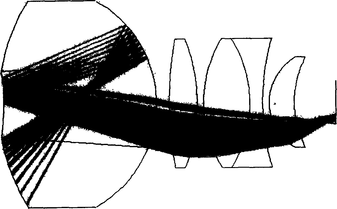
[0016] The 180° large field of view annular panoramic imaging method uses a cylindrical plane projection imaging method to replace the central projection imaging method in traditional optics, and is a new concept imaging method.

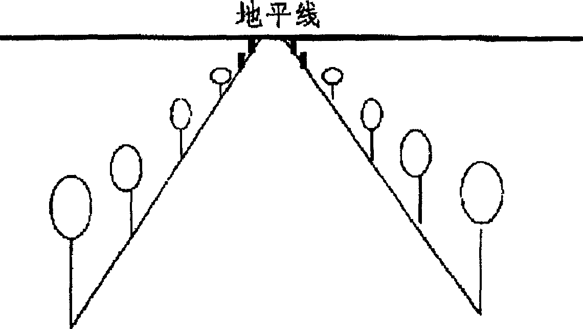
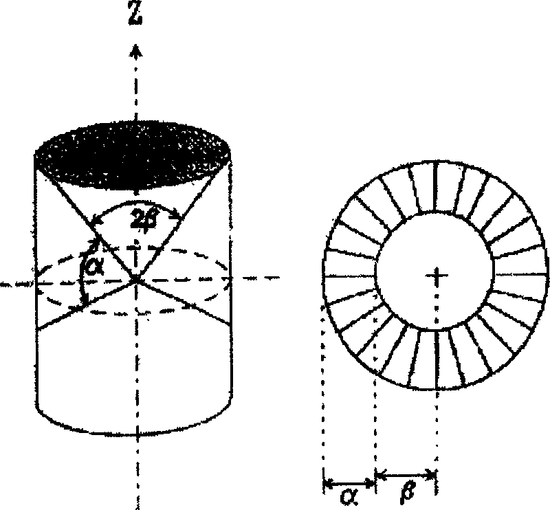
[0017] If the three-dimensional space is regarded as a cylinder instead of a spherical body, the image can be expanded into a plane by the method of stretching, and the three-dimensional cylinder is represented by a two-dimensional plane. This projection method is called cylindrical planar projection, and it is the basis for the imaging of annular panoramic lenses. In cylindrical planar mapping, all parallel rays focus on a point, and the vanishing point is the center of the circle. In the traditional central projection method, parallel lines of different directions are focused on different points of a (horizontal) line. image 3 is a schematic illustration of the cylindrical planar projection and shows the limiting angles that determine the field o...


PUM


Abstract

The present invention discloses one kind of 180 deg large view field annular panoramic staring image method. It adopts cylindrical plane projection method, twice reflecting annular lens for the first imaging to realize the annular panoramic staring imaging, relay lens for the second imaging to obtain real image, planar photoelectronic imaging device receiving and displaying 3D panoramic staring image with infinite field depth. The present invention has the advantages of large view field of 180 deg, no motion part, small size, light structure, infinite field depth and no need of focusing to form clear image, and may be used in panoramic machine vision, tunnel and pipe inner wall detection, medical endoscopic imagig, bank safety monitoring, panoramic 360 deg photography, etc.

Description

technical field [0001] The invention relates to a circular panoramic staring imaging method with a large field of view of 180°. Background technique [0002] figure 2 It is a schematic diagram of the traditional optical imaging method-central projection method, which is a model of visual optics. When the human eye observes the surrounding scenery, visual optics follows the principle of central projection, that is, objects of the same size that are closer to the eyes will appear larger than the distance. When it is far away, it is larger, that is, there is a phenomenon that the distance is smaller and the near is larger. Make the human eye feel far and near, and the three-dimensional space is presented in front of our eyes. In order to compress the three-dimensional space into a two-dimensional plane. This is the central projection method. If you want to use a picture to describe the three-dimensional space, you should also draw the distant sc...

Claims


Application Information

Patent Timeline
IPC IPC(8): G02B13/06G02B13/18G03B15/08G06T11/00
Inventor 白剑杨国光侯西云
Owner ZHEJIANG UNIV
Why Eureka
Try Eureka