Laser processing method for connecting rod splitting groove and its equipment

A laser processing method and laser processing technology, used in laser welding equipment, metal processing equipment, connecting rod bearings, etc., can solve the problem of affecting the machining accuracy of the big head hole. The assembly quality of the connecting rod body and the connecting rod cover, the poor meshing of the fracture surface, and the fracture It can improve the fracture effect, good dimensional accuracy, and avoid the slag drop.

Inactive Publication Date: 2005-01-05
JILIN UNIV
View PDF15 Cites 21 Cited by
  • Summary
  • Abstract
  • Description
  • Claims
  • Application Information

AI Technical Summary

Problems solved by technology

When the grooves on both sides of a connecting rod are inconsistent, the two sides are not cracked at the same time during the fracture process, and the side after the fracture is often torn, and the fracture surface is slag and deformed. Assembly quality of body and connecting rod cover

Method used


Image

  • Laser processing method for connecting rod splitting groove and its equipment
  • Laser processing method for connecting rod splitting groove and its equipment
  • Laser processing method for connecting rod splitting groove and its equipment

Examples


Embodiment Construction

[0037] The method and equipment of the present invention will be further described in detail in the following embodiments given in conjunction with the accompanying drawings.

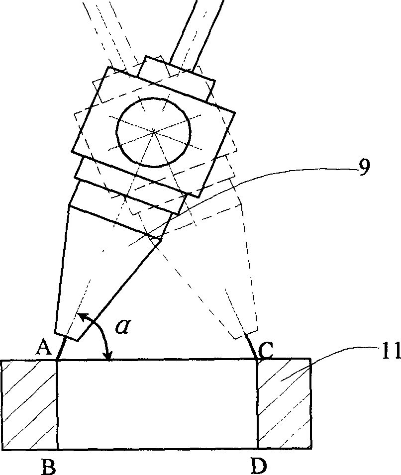
[0038] refer to image 3 , the laser processing method of the prefabricated cracking groove before the splitting of the connecting rod fracture of the present invention is characterized in that it is carried out according to the following steps:

[0039] a. The laser cutting head 9 of the laser processing equipment corresponds to point A of the upper end of the cutting part on the side of the big head hole of the connecting rod 11 fixed on the workbench;

[0040] b. Adjust the laser cutting head so that the laser incident angle (that is, the angle between the laser beam and the surface normal of the workpiece to be cut) α is 0°-70°, turn on the laser, and the laser cutting head moves vertically downward to cut between the connecting rod At point B at the lower end of the big head hole, complete the AB cu...


PUM


Abstract

A method for using laser to premachine the cracking slots before dividing connecting rods from each other includes such steps as fixing the laser cutting head above the position to be machined, which is near the hole on big end of connecting rod, regulating the incident angle of laser beam to 0-70 deg.C, turning on laser device, vertically moving the laser cutting head to machine the cracking slot to predefined depth, and repeating said steps to machine another cracking slot at another end of aconnecting rod.

Description

technical field [0001] The invention relates to a laser processing method and special equipment for prefabricating cracking grooves before splitting of connecting rods. Background technique [0002] as attached figure 1 , 2 As shown, the connecting rod is a dissected part made up of the connecting rod body 3 and the connecting rod cover 2. During actual work, the connecting rod body 3 and the connecting rod cover 2 are assembled together for use. There are two main traditional connecting rod manufacturing processes: (1) integral forging or powder sintering forming of connecting rod → cutting and separation → machining of rod and cover joint surface → machining of rod and cover bolt hole → assembly. (2) Connecting rod body and connecting rod cover are respectively forged and formed→machined rod and cover joint surface→machined rod and cover bolt hole→assembled. The above process not only needs to broach, mill and grind the joint surface of the connecting rod body and the c...

Claims


Application Information

Patent Timeline
Patent Type & Authority Applications(China)
IPC IPC(8): B23D31/00B23K26/38F16C9/04
CPCF16C9/045
Inventor 寇淑清杨慎华赵勇金文明张弛邓春萍
Owner JILIN UNIV
Why Eureka
Try Eureka