
Whole field optical measuring method for high speed complex flow field, and its measurer

An optical measurement, complex technology, applied in the direction of measuring devices, fluid velocity measurement, velocity/acceleration/shock measurement, etc.

Inactive Publication Date: 2005-01-12
TIANJIN UNIV
View PDF0 Cites 24 Cited by
  • Summary
  • Abstract
  • Description
  • Claims
  • Application Information

AI Technical Summary

Problems solved by technology

[0007] The purpose of the present invention is to provide a full-field optical measurement method and measurement device for high-speed and complex flow fields, which fundamentally solves the measurement upper limit problem of cross-correlation DPIV, thereby improving measurement accuracy

Method used


Image

  • Whole field optical measuring method for high speed complex flow field, and its measurer
  • Whole field optical measuring method for high speed complex flow field, and its measurer
  • Whole field optical measuring method for high speed complex flow field, and its measurer

Examples


Embodiment Construction

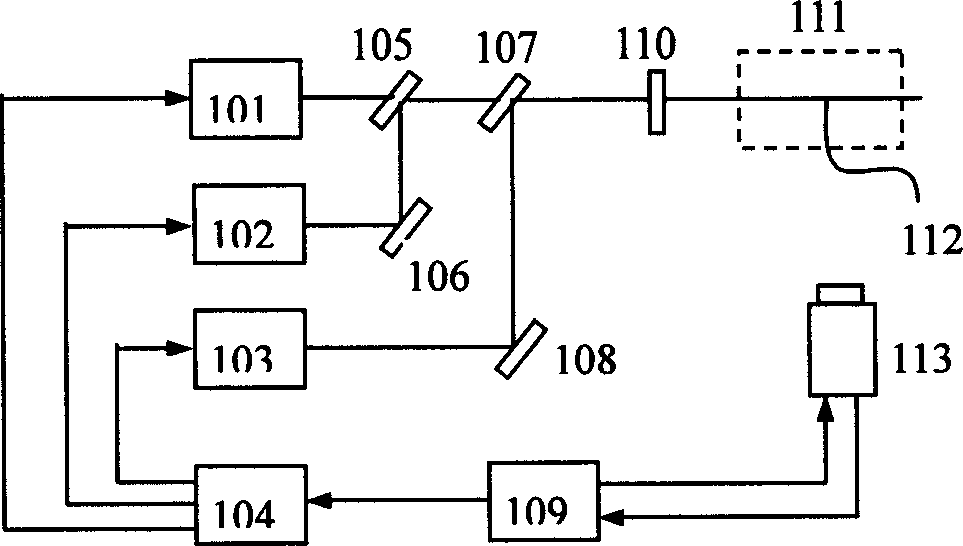
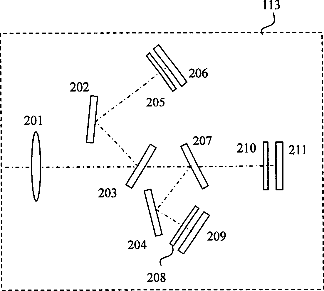
[0018] The specific implementation method of the present invention will be described in detail below in conjunction with the accompanying drawings. as attached figure 1 As shown, the wavelengths generated by lasers 101, 102 and 103 are λ 1 ,λ 2 and lambda 3 The pulsed laser light is combined into one beam by the combined beam path composed of mirrors 105, 106, 107 and 108. The cylindrical mirror 110 converts the laser beam into a laser sheet light 112 to illuminate the measured flow velocity field 111, and the plane where the sheet light is located is the measured flow velocity field plane. The multi-CCD cameras 113 are located in a direction perpendicular to the laser sheet light 112 or at an included angle θ, imaging particles in the plane of the flow velocity field illuminated by the laser sheet light 112 and recording particle images.

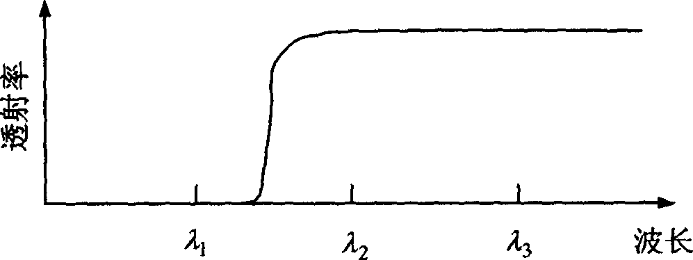
[0019] The multi-CCD camera 113 is composed of an imaging lens 201, a light splitting path, an interference filter, and three independ...


PUM


Abstract

The method includes techniques of spectral time sequence multiplexing and spectral separation. The procedure includes following arranged steps: using laser in three different wavelengths as illumination light at different delta t pulse time intervals illuminate flow field to be measured; three independent CCDs record image for same object space; each CCD records particle image illuminated by corresponding wavelength; eliminating measuring upper limit of cross correlation DPIV. The device includes pulsed laser, time schedule controller for pulsed laser, beam splitter and multiple CCD camera. Advantages are: full-field measurement and high measuring precision.

Description

technical field [0001] The invention relates to a full-field optical measurement method and a measurement device of a high-speed complex flow field, belonging to the technical field of flow field testing. Background technique [0002] Full-field measurement of high-speed complex structure flow field is a key technology for studying aerodynamics, combustion and other issues in aerospace and other fields. Particle Image Velocimetry (PIV for short) is based on flow display technology and uses computer image processing technology to quantitatively obtain flow field information from recorded particle images. Early PIV uses photosensitive film, and uses double-exposure or multiple-exposure techniques to record particle images to form PIV negatives. Using optical Young's fringe method or particle image correlation to process the PIV film point by point, and obtain the average displacement of the particle image in the small area of ​​each interpretat...

Claims


Application Information

Patent Timeline
IPC IPC(8): G01M10/00G01P5/00
Inventor 李恩邦姚建铨郁道银习江涛奇卡罗
Owner TIANJIN UNIV
Learn More