Method for preparing photon crystal optical fibre and apparatus therefor
A technology of photonic crystal optical fiber and optical fiber preform, which is applied in glass manufacturing equipment, manufacturing tools, glass production, etc., and can solve problems such as external pollution, large loss of photonic crystal optical fiber, and slow drawing speed
- Summary
- Abstract
- Description
- Claims
- Application Information
AI Technical Summary
Problems solved by technology
Method used
Image
Examples
preparation example Construction
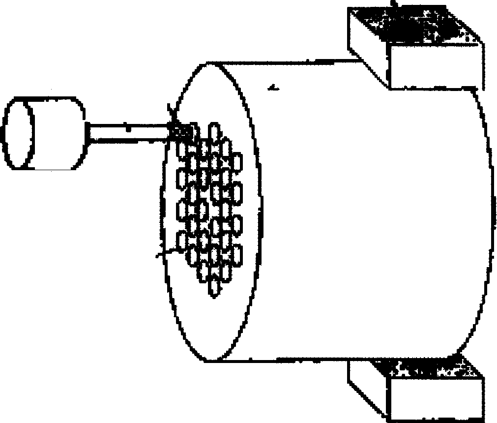
[0077] First, the specific steps of the photonic crystal fiber preparation method of the present invention are described in detail: a high-purity glass tube of a certain size is drawn on a wire drawing machine or other equipment into a thin glass tube, and after it is cut to a certain length, it is then used on a wire drawing machine or other equipment. Pull on the equipment to make a thinner glass tube, and repeat it many times until a thin glass tube of suitable size is obtained. The nominal outer diameter of the thin glass tube is generally controlled within the range of 1-10mm as required. The finished thin glass tube can also be used directly. In a glass sleeve with a predetermined inner diameter and outer diameter, a plurality of the aforementioned thin glass tubes are arranged into a specific structure according to a certain rule to form a photonic crystal fiber preform. The gaps between the thin glass tubes and the glass sleeve can be filled with high-purity solid thin gla...
no. 1 example
[0081] The high-purity quartz glass tube is drawn on the drawing tower to make round quartz thin glass tubes and thin glass rods of different specifications. Insert a round quartz thin glass tube with a wall thickness of 1.0mm, an outer diameter of 4.5mm and a length of 1000mm (that is, the specification of the quartz thin glass tube is φ4.5×1.0), and insert the attached Figure 5 In the circular jacks on the vacuum cover 52 and the insert plate 53 shown, the jacks are in a hexagonal lattice, and the number of lattice layers is 7. That is, the quartz thin glass tube is in a hexagonal lattice. The number of layers is 7 layers, the middle layer is thin glass tubes, and each thin glass tube is sealed by placing a φ3.0mm sealing ring between the vacuum cover 52 and the inserting plate 53. The length of the thin glass tube in the space A part does not exceed 20mm. After the cylindrical pressure cover 51, the vacuum cover 52 and the insert plate 53 are tightened, the φ60.0×3.0mm pure qu...
no. 2 example
[0085] The high-purity fluoride glass tube is drawn on the drawing tower to make round thin glass tubes and thin glass rods of different specifications. Insert a fluoride quartz thin glass tube with a wall thickness of 1.5 mm, an outer diameter of 5.0 mm, a wall thickness of 1.0 mm, an outer diameter of 4.0 mm, and a length of 1000 mm into the attached Figure 5 In the circular jacks on the vacuum cover 52 and the insert plate 53, the jacks are in a hexagonal lattice, and the number of lattice layers is 11, that is, the quartz thin glass tube is in a hexagonal lattice. The number of layers is 11, the middle layer is a solid thin rod doped with rare earths, the specification of the 6-layer thin glass tube in the inner ring is φ4.0×1.0, and the specification of the 4-layer thin glass tube in the outer ring is φ5.0×1.5. Each thin glass tube is sealed by a suitable size sealing ring placed between the vacuum cover 52 and the inserting plate 53. The length of the thin glass tube in the...
PUM
 Abstract
Description
Claims
Application Information
 - R&D
- Intellectual Property
- Life Sciences
- Materials
- Tech Scout
- Unparalleled Data Quality
- Higher Quality Content
- 60% Fewer Hallucinations
Browse by: Latest US Patents, China's latest patents, Technical Efficacy Thesaurus, Application Domain, Technology Topic, Popular Technical Reports.
© 2025 PatSnap. All rights reserved.Legal|Privacy policy|Modern Slavery Act Transparency Statement|Sitemap|About US| Contact US: help@patsnap.com


