Full light wave converter based on laser four wave mixing effect

A wavelength converter and four-wave mixing technology, which is applied to lasers, laser components, semiconductor lasers, etc., can solve problems such as high cost and complex device structure, and achieve low cost, adjustable conversion wavelength, and simple structure.

Inactive Publication Date: 2005-03-02
UNIV OF SHANGHAI FOR SCI & TECH
View PDF0 Cites 15 Cited by
  • Summary
  • Abstract
  • Description
  • Claims
  • Application Information

AI Technical Summary

Problems solved by technology

[0008] The present invention is to solve the problem that the existing all-optical wavelength conversion device based on the four-wave mixing effect needs to provide pumping light with stable wavelength and narrow linewidth, which makes the device structure complicated and high in cost. It provides a fiber grating based The all-optical wavelength conversion device of the four-wave mixing effect in the external cavity semiconductor laser, it does not need an additional pump light source, has a simple structure, low cost, and has the outstanding advantages of high conversion wavelength stability and adjustable conversion wavelength

Method used


Image

  • Full light wave converter based on laser four wave mixing effect
  • Full light wave converter based on laser four wave mixing effect

Examples


Embodiment 1

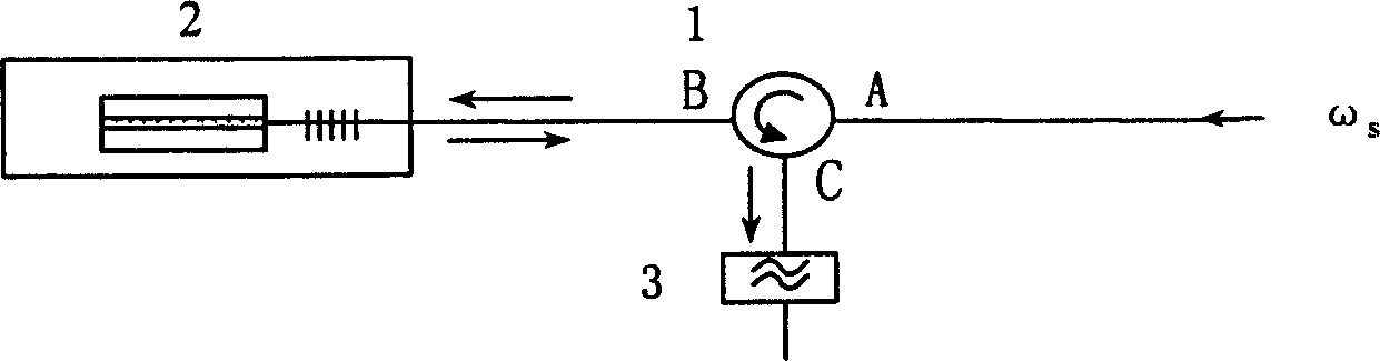
[0017] Embodiment one: fiber grating external cavity semiconductor laser as an all-optical wavelength conversion device ( figure 1 )

[0018] The signal light is input from the A port of the circulator 1, and injected into the fiber grating external cavity semiconductor laser through the B port. The signal light (frequency ωs) in the active medium of the laser produces a four-wave mixing effect with the pumping laser (frequency ωp) to generate a conjugate wave (frequency 2ωp-ωs) as the converted output signal.

[0019] The converted output signal enters the B port of circulator 1, and then is coupled out by the C port. Using a fiber optic circulator for coupling between the signal and the semiconductor laser chip can improve the coupling efficiency, reduce the influence of the converted signal light and the light source feedback light on the signal light source, and increase the output power of the converted signal.

[0020] The converted output signal coupled from the C por...

Embodiment 2

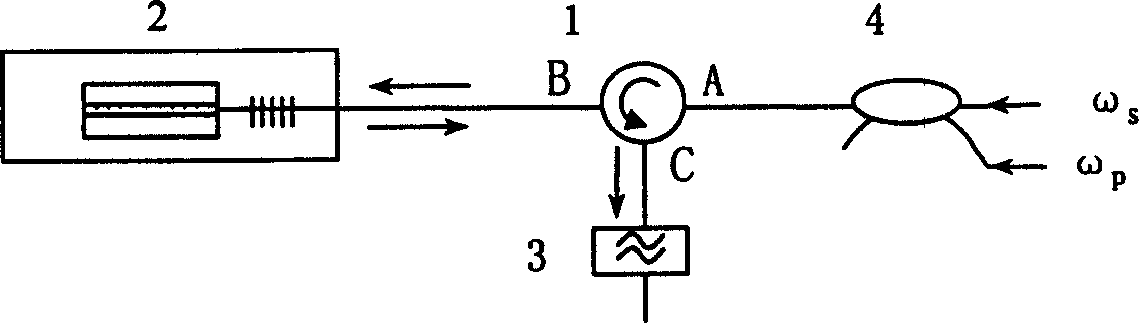
[0021] Embodiment two: fiber grating external cavity semiconductor laser is used as an all-optical wavelength conversion device for converting an output light source ( figure 2 )

[0022] The signal light (frequency ωs) and continuous pump light (frequency ωp) enter the A port input of the circulator 1 through the coupler 4, and are injected into the fiber grating external cavity semiconductor laser 2 through the B port. The working current of the laser 2 is adjusted, and the laser 2 is in a critical excitation state (not yet excited) under the condition that only continuous pumping light is injected. When a "1" signal is injected, the signal light and the pump light will generate a conjugate wave (frequency is 2ωp-ωs), and the excitation frequency of the fiber grating external cavity semiconductor laser 2 is selected to be 2ωp-ωs, then the conjugate wave will be Quite an "injection seed" to excite the laser 2 as the converted signal light. Because the frequency of the conj...


PUM


Abstract

The invention discloses an all optical wavelength converter based on laser four-wave frequency mixing effect, composed of a laser, a looper and a filter, where the laser is an optical-fiber grating external-cavity semiconductor laser, a signal at angular frequency of omega s is injected through the looper to the laser and generates the four-wave frequency-mixing effect with the pumping light at angular frequency of omega p in an active medium so as to generate a conjugate light at angular frequency of 2 omega p-omega s, forming a conversion output signal, which is coupledly inputted to the filter through the looper, thus realizing the wavelength conversion. As compared with the SOA-based wavelength converter, it needs no additional pumping light source because the laser directly provides wavelength conversion, simple-structural and low-cost; it adopts optical-fiber grating, therefore it has the advantages of high stability of wavelength conversion, and regulable wave conversion.

Description

technical field [0001] The invention relates to an optoelectronic device for optical fiber communication, in particular to an all-optical wavelength converter with four-wave mixing effect. Background technique [0002] Wavelength division multiplexing technology is the preferred technology for high-speed broadband and large-capacity optical fiber communication. In an optical cross-connect node of a wavelength division multiplexing communication system, when two signals of the same wavelength in different optical fibers enter the same optical fiber, the problem of wavelength blocking occurs. Due to the limitations of various factors in the system, the number of wavelengths that can be multiplexed by each fiber is limited, so this situation will inevitably occur at the optical cross node. An effective way to solve this problem is to use wavelength conversion technology to convert one of the signal wavelengths to other wavelengths, thereby avoiding wavelen...

Claims


Application Information

Patent Timeline
Patent Type & Authority Applications(China)
IPC IPC(8): G02F1/35H01S5/00H04J14/02
Inventor 马军山张嵬
Owner UNIV OF SHANGHAI FOR SCI & TECH
Why Eureka
Try Eureka