Vacuum deposition equipment

A vacuum coating and equipment technology, applied in vacuum evaporation coating, sputtering coating, ion implantation coating, etc., can solve problems such as substrate pollution, improve production efficiency, reduce total energy consumption of pumping, and The effect of time reduction

Inactive Publication Date: 2005-03-16
储继国
View PDF2 Cites 12 Cited by
  • Summary
  • Abstract
  • Description
  • Claims
  • Application Information

AI Technical Summary

Problems solved by technology

That is to say, during the pumping process, the coating chamber must pass through the pressure range of 1-50Pa with the highest oil return rate. Therefore, the oil vapor from the backing pump will still enter the coating chamber in large quantities, causing serious pollution to the substrate.

Method used


Image

  • Vacuum deposition equipment
  • Vacuum deposition equipment

Examples


Embodiment Construction

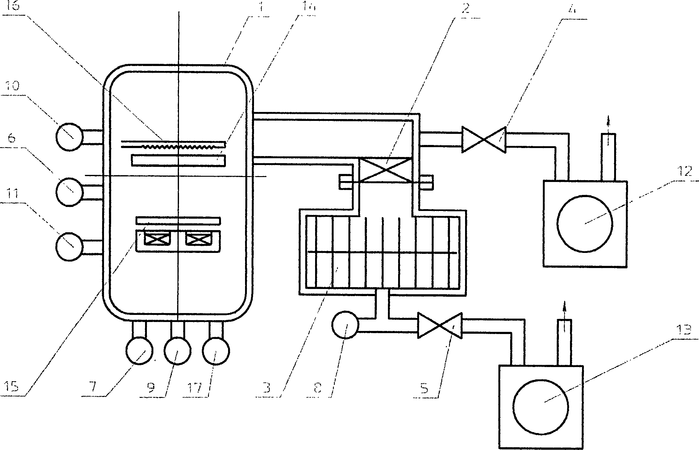
[0021] see figure 1 , the vacuum coating equipment of the first embodiment of the present invention consists of a coating chamber 1, a high vacuum valve 2, a molecular traction pump 3, low vacuum valves 4 and 5, a high vacuum gauge 6, low vacuum gauges 7 and 8, a discharge power supply 9, a high Pure argon 10, protective gas (industrial nitrogen, or dry air) 11, backing vacuum pumps 12 and 13, substrate 14, magnetron target 15, heater 16 and heater power supply 17 are composed.

[0022] Substrate 14, magnetron target 15 and electric heater 16 are located in coating chamber 1, high vacuum valve 2, low vacuum valve 4, high vacuum gauge 6, low vacuum gauge 7, discharge power supply 9, high-purity argon gas 10, protection The gas 11 and the heater power supply 17 are respectively connected to the coating chamber 1, the fore vacuum pump 12 is connected to the low vacuum valve 4, the air inlet of the traction molecular pump 3 is connected to the high vacuum valve 2, and the exhaust ...


PUM


Abstract

The invention discloses a vacuum plating equipment, which comprises filming chamber, backing vacuum pump, high vacuum valve, soft vacuum valve, high vacuum gage, vacuometer and film source, and molecular drag pump. Molecular drag pump air admission port is connected with filming chamber, air exhaust opening is connected with backing pump, and air flow dust arrester is installed between molecular drag pump bearing and bleed-off passage. The inventive vacuum film coating equipment has a simple structure, low energy consumption, high production efficiency, short air exhaust time, and promote the vacuum filming product quality, specificly apply to vacuum filming field sensitive to oil steam contamination.

Description

【Technical field】 [0001] The invention relates to a coating device, in particular to a vacuum coating device. 【Background technique】 [0002] Traditional vacuum coating equipment uses backing pumps (low vacuum pumps, such as oil-sealed rotary vane mechanical vacuum pumps, slide valve vacuum pumps), Roots pumps (medium vacuum pumps) and oil diffusion pumps (high vacuum pumps), which have complex structures and high energy consumption. , Long pumping time, low production efficiency, large oil vapor pollution and low quality of coating products. [0003] In the past ten years, some vacuum coating equipment have adopted turbomolecular pumps as high vacuum pumps, basically eliminating oil vapor pollution during high vacuum operation. However, the maximum working pressure of the inlet of the turbomolecular pump is 1-10Pa (Pascal), so the pressure of the coating chamber must be pumped down to below 10Pa by the backing pump before the pump can start working. That is to say, during...

Claims


Application Information

Patent Timeline
Patent Type & Authority Applications(China)
IPC IPC(8): C23C14/56
Inventor 储继国
Owner 储继国
Why Eureka
Try Eureka