Sensor cell, biosensor, capacitive device manufacturing method, biological reaction detection method, and gene analyzing method

A sensor unit and biosensor technology, applied in the field of biosensors, can solve problems such as inability to perform real-time detection, difficulty in real-time detection of hybridization, and large instruments

Inactive Publication Date: 2005-03-30
SEIKO EPSON CORP
View PDF0 Cites 4 Cited by
  • Summary
  • Abstract
  • Description
  • Claims
  • Application Information

AI Technical Summary

Problems solved by technology

[0003] However, in order to detect the fluorescence reaction etc. by optical means in the above-mentioned DNA microarray, not only the instrument becomes very large, but also it is difficult to detect the hybridization in real time.
Similarly, in the automatic sequencer method using the Sanger method, the fluorescent dye-labeled DNA fragments are separated by gel electrophoresis, the dyes of the labeled fragments are excited by irradiating laser light, and the signals are detected by a fluorescent detector. Not only does the instrument become very large , and also cannot detect in real time

Method used


Image

  • Sensor cell, biosensor, capacitive device manufacturing method, biological reaction detection method, and gene analyzing method
  • Sensor cell, biosensor, capacitive device manufacturing method, biological reaction detection method, and gene analyzing method
  • Sensor cell, biosensor, capacitive device manufacturing method, biological reaction detection method, and gene analyzing method

Examples


Embodiment approach 1

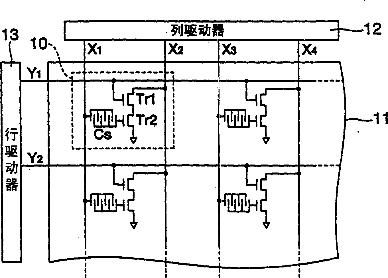
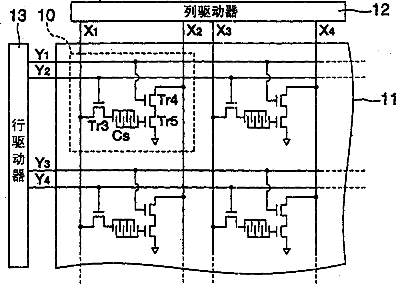
[0038] figure 1It is the main circuit configuration diagram of the biosensor. This sensor is equipped with: the sensor unit 10 that is arranged in the matrix shape of N row M column on the substrate 11, constitutes sensor unit matrix; The column driver 12 of the column selection line X1, X2, ...; a group of sensor units 10 arranged side by side in the row direction of the sensor unit matrix is ​​selected, and the drive is used to switch the sensor function on the sensor unit 10. Row selection line Y 1 , Y 2 , . . . the row driver 13 . The sensor unit 10 is a sensor for detecting the hybridization of the probe DNA and the target DNA in the reaction cell as an electrical signal, and is equipped with: a capacitor Cs for detecting DNA hybridization based on capacitance change; The switching transistor Tr1 for switch control of the sensing function; the converter (signal conversion element) that converts the hybridization between the probe DNA and the target DNA in the reaction...

Embodiment approach 2

[0050] Hereinafter, this embodiment will be described with reference to each drawing.

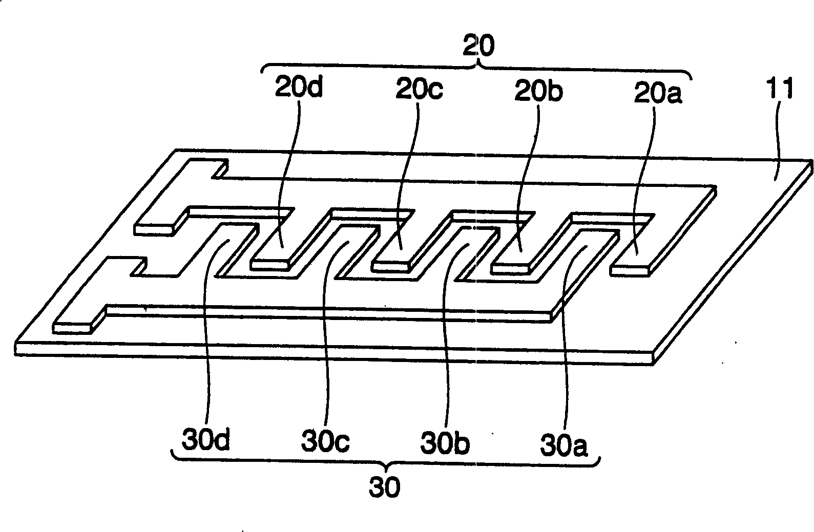
[0051] Figure 5 It is a top view of Embodiment 2 of a capacitor. In the present embodiment, by providing insulating film 40 between comb-shaped electrode 20 and comb-shaped electrode 30 facing each other at a slight interval, the distance between the opposing electrodes is made as narrow as possible. In this way, by narrowing the distance between the electrodes, the capacitance of the capacitor can be increased and the sensitivity of the sensor can be improved. The insulating film 40 is a film that isolates the comb-toothed electrodes 20 and the comb-toothed electrodes 30 without communication (short-circuiting), and can also be called a separation wall, a partition wall, a separation member, a separation member, or a partition. member. As the insulating film 40, for example, an organic insulating material such as polyimide is suitable. As described below, surface treatment with polyim...

Embodiment approach 3

[0060] Hereinafter, this embodiment will be described with reference to each drawing.

[0061] Figure 8 It is a plan view of Embodiment 3 of the capacitor Cs. In this embodiment, the capacitor Cs is constituted by a pair of arcuate opposing electrodes (electrodes 80 , 90 ). The electrode 80 includes substantially concentric electrode portions 80a, 80b, and 80c each having a different inner diameter, and the electrode 90 includes substantially concentric electrode portions 90a, 90b, and 90c each having a different inner diameter. In these electrode parts, the positive electrode and the negative electrode are arranged alternately, between the inner peripheral surface of the electrode part 80a and the outer peripheral surface of the electrode part 90a, between the inner peripheral surface of the electrode part 90a and the outer peripheral surface of the electrode part 80b, ..., the electrode A micro capacitor is formed between the inner peripheral surface of the portion 80c an...


PUM


Abstract

The present invention provides a biosensor which comprises: a sensor matrix where sensor cells are arrayed in a matrix, a row driver for supplying a predetermined voltage signal to sensor cells arrayed in the row direction of the matrix, and a column driver for supplying a predetermined voltage signal to sensor cells arrayed in the column direction of the matrix. Each of the sensor cells has: a capacitive element (Cs) composed of a pair of opposed electrodes on which a probe DNA immobilized on the electrode surface selectively reacts with the target DNA; a transistor (Tr2) for varying the value of the current outputted from a drain terminal in response to the variation of the capacitance of the capacitive element (Cs) caused by DNA hybridization, and a switching element (Tr1) for supplying a voltage signal supplied from the column driver to the current input terminal of the transistor (Tr2).

Description

technical field [0001] The present invention relates to a biosensor used for gene analysis, biological information analysis, and the like. Background technique [0002] In recent years, with the progress of the genome project, the genetic structure of each organism has been gradually elucidated. In order to link this result with the analysis of life phenomena, the deciphering of the base sequence of DNA and the functional analysis of genetic information are becoming research topics. As a system for simultaneously monitoring the expression levels of all genes in cells, a DNA microarray can be used. In this array, the reverse transcription reaction of mRNA or total RNA extracted from cells or tissues is performed to prepare probe DNA, and after high-density dot printing on substrates such as glass slides, the fluorescent dye-labeled target DNA contains the probe DNA. The target DNA hybridization of the base sequence complementary to the DNA, the fluorescence pattern is observ...

Claims


Application Information

Patent Timeline
Patent Type & Authority Applications(China)
IPC IPC(8): G01N27/22G01N33/543
CPCG01N33/5438G01N27/22G01N27/228G01N27/3276
Inventor 前田浩
Owner SEIKO EPSON CORP
Why Eureka
Try Eureka