Plasma coupling light catalytic unit assembly and gas purifier therewith

A photocatalytic unit and plasma technology, which is applied in household heating, lighting and heating equipment, space heating and ventilation, etc. It can solve the problems of difficult discharge of chemical components, complicated electrode processing technology, and inability to achieve complete decomposition. , to achieve the effects of reduced production cost, improved processing effect, and convenient processing

Inactive Publication Date: 2005-05-11
UNIV OF SCI & TECH OF CHINA
View PDF1 Cites 19 Cited by
  • Summary
  • Abstract
  • Description
  • Claims
  • Application Information

AI Technical Summary

Problems solved by technology

The problem with this method is that it is necessary to change the reaction agent frequently, which is not only troublesome, but also difficult to control the discharge of the agent components.
In addition, when decomposing and removing harmful components such as formaldehyde, a catalyst reaction with a high oxidation-reduction potential must be carried out. The problem is that the oxidative decomposition with ozone does not achieve complete decomposition, but stops at the stage where the product is decomposed in the middle. Complete harmlessness cannot be achieved
Although the device has a good degradation effect on organic matter and can be used for deodorization and purification of harmful gases, etc., since the gas containing harmful substances in the device must pass directly through the two electrodes, the electrodes must be made into a porous structure. Its strength is poor, and it is easy to be corroded, so it must be repaired and replaced frequently; at the same time, it complicates the processing technology of the electrode and increases the manufacturing cost

Method used


Image

  • Plasma coupling light catalytic unit assembly and gas purifier therewith
  • Plasma coupling light catalytic unit assembly and gas purifier therewith
  • Plasma coupling light catalytic unit assembly and gas purifier therewith

Examples


Embodiment Construction

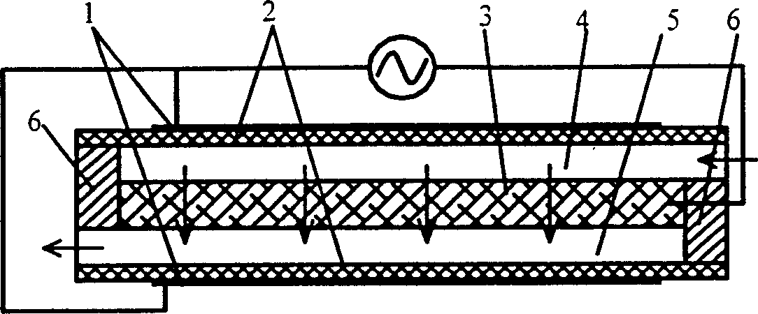
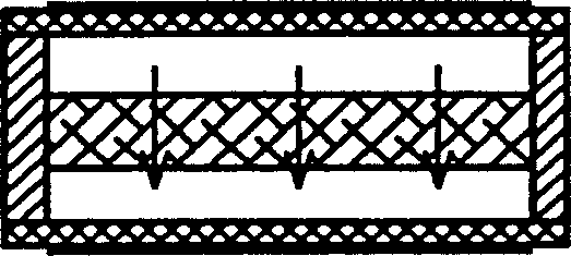
[0023] see figure 1 , figure 2 , two parallel dielectric barrier layers 2 are ceramic flat plates with a thickness of 1 mm, and a copper film with a thickness of 0.02-0.1 mm is plated on the outer side of the ceramic plate 2 (the back side of the discharge gap) as the electrode 1, The flat photocatalytic porous body 3 is a mesh made of copper wire with a diameter of about 0.5 mm. The mesh is about 2 mm, and 12 pieces are stacked. The total thickness is about 6 mm. The photocatalyst is attached to the mesh by coating. The film is titanium oxide TiO 2(anatase type), there is a gap of 5 mm between the dielectric barrier layer 2 and the photocatalytic porous body 3 respectively. The sealing member 6 made of engineering plastics connects the two planar photocatalytic porous bodies into a whole, and forms a sealed inner space. The air inlet 4, the air outlet 5 on the side wall and the holes on the porous photocatalyst 3 constitute a smooth airflow channel, and the flow direction...


PUM


Abstract

A plasma coupled photocatalyzing module used for gas purifier is composed of the plate electrodes with rigid dielectric barrier layer on its inner surface, the porous photocatalytizing body arranged between two dielectric barrier layers, and the sealing apron arranged to the peripheries of two dielectric barrier layers to form two spaces (one having gas inlet and another having gas outlet). Said gas purifier is composed of at least one said module.

Description

technical field [0001] The invention relates to a gas purification device for photocatalyzing and plasma decomposition, oxidation, reduction and degradation of bacteria, viruses, odors and harmful substances contained in gas. Background technique [0002] In recent years, due to the closed development of high-rise residential buildings and the increasingly serious outdoor air pollution, how to improve the air quality of living spaces has attracted more and more attention. For example, how to reduce harmful components such as formaldehyde, benzene, banana water and other VOCs slowly released from bacteria, viruses, tobacco waste gas contained in the air, building materials and decoration, and furniture, as well as metabolic odor in the environment. [0003] In the prior art, adsorbents such as activated carbon are usually used for deodorization, or to make odor components react with other pharmaceutical components to become harmless substances to achieve the purpose of reduci...

Claims


Application Information

Patent Timeline
Patent Type & Authority Applications(China)
IPC IPC(8): F24F3/16
Inventor 黄卫东夏维东王大志
Owner UNIV OF SCI & TECH OF CHINA
Why Eureka
Try Eureka