

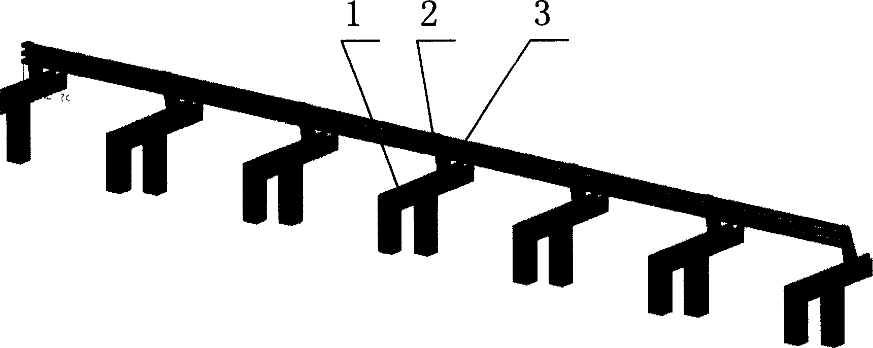
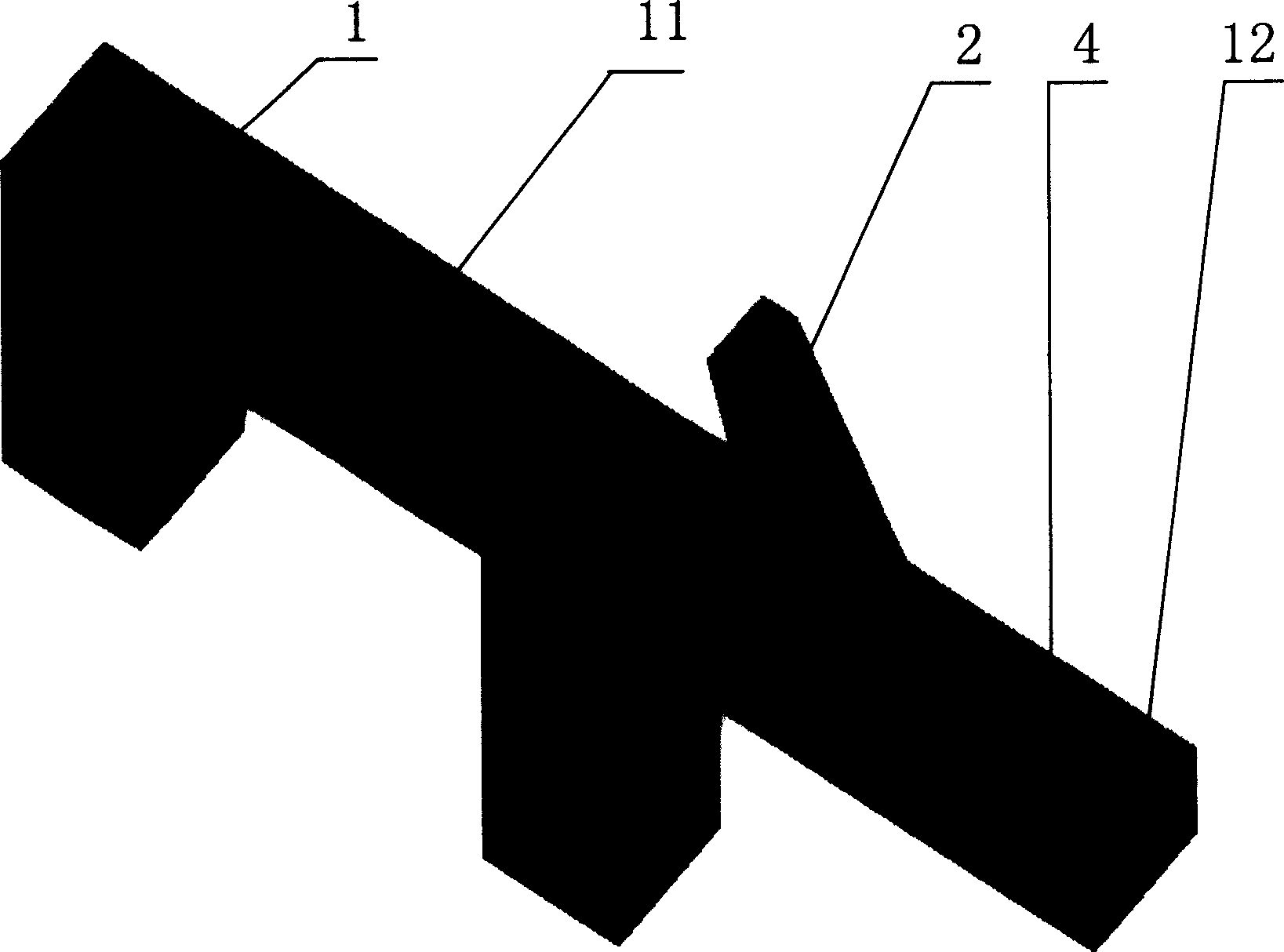
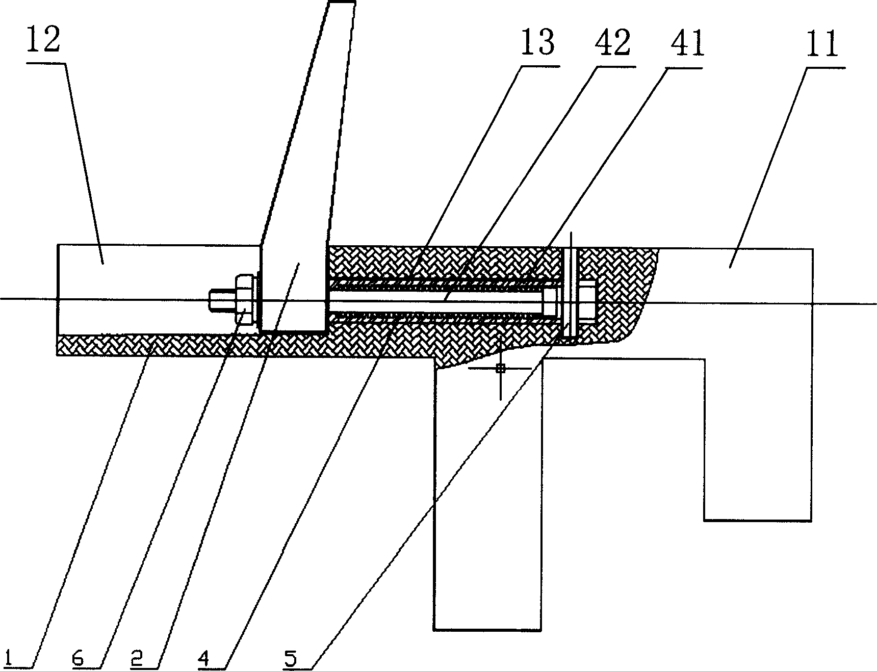
Crashproof guard bar
An anti-collision guardrail and guardrail technology, applied in bridge parts, roads, bridges and other directions, can solve the problems of vehicle rollover, reduction of the effective height of guardrails, large windward area, etc., and achieve the effect of good guiding ability
- Summary
- Abstract
- Description
- Claims
- Application Information
AI Technical Summary
Problems solved by technology
Method used
Image

Examples
Embodiment Construction
[0024] According to the momentum theorem, if a particle changes its velocity sharply in a very short time, while its position remains almost unchanged, the particle is subject to a collision. Assuming that the mass of the objects participating in the collision remains unchanged during the collision, the time interval Δt is integrated by Newton's law, and the change of momentum is equal to the impulse, namely:
[0025] I'=mv s ′ The momentum of the particle after the collision
[0026] I = mv s The momentum of the particle before the collision
[0027] P = ∫ t t ′ Fdt The momentum of the particle
[0028] I'-I=P
[0029] During the entire collision process, F is a variable, which is a function of time, but it can be approximately considered to be a constant value in each time interval Δt, then:
[0030] ...
PUM
 Abstract
Description
Claims
Application Information