Composite coding multiresolution three-dimensional digital imaging method

A three-dimensional digital, multi-resolution technology, applied in instruments, measuring devices, optical devices, etc., can solve the problems of lack of three-dimensional data, phase blur, error propagation, etc.

Inactive Publication Date: 2005-06-29
SHENZHEN UNIV
View PDF2 Cites 29 Cited by
  • Summary
  • Abstract
  • Description
  • Claims
  • Application Information

AI Technical Summary

Problems solved by technology

However, when there is a discontinuous area or a large change in the surface gradient of the measured object, or there is an information blind area, the phase unwrapping of

Method used


Image

  • Composite coding multiresolution three-dimensional digital imaging method
  • Composite coding multiresolution three-dimensional digital imaging method
  • Composite coding multiresolution three-dimensional digital imaging method

Examples


Embodiment Construction

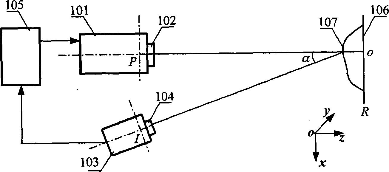
[0044] According to the above-mentioned method, the device for realizing composite encoding and multi-resolution three-dimensional digital imaging mainly includes a digital projection lighting transmitter, an image sensing receiver and an image processor. Said digital projection lighting transmitter can be a digital liquid crystal projection device (LCD projector), a digital micromirror projection device (DMD projector) or a silicon substrate liquid crystal projection device (LCOS projector), which can be conveniently provided by a computer image processing system. Generate two-dimensional dot matrix and fringe graphics and write them into a digital projection device; said image sensing receiver includes an optical imaging lens and a photodetector, and the optical imaging lens can be an imaging lens or lens group with a fixed focal length or a variable focal length, Binary optical imaging system, diffraction element imaging system, microscopic imaging system; said photodetectio...


PUM


Abstract

This invention discloses a three-dimension image forming method by use of compound code multi-resolution, that is the three-dimension digit technique based on the combination of lattice project and strip project. The method adopts the image-forming device composed of digit project shining emitter, image sensor receiver and image processor. It is first to use lattice project three-dimension digit image-forming without phase fussy characteristics and to get the three-dimension depth image of low resolution rate with lattice code and to project the strip onto the object surface; to use the characteristics of high accuracy of space phase modulation; to de the phase extension by combination with acquired object low resolution rate and to further get the accurate three-dimension image with multi-resolution of the object to be measured.

Description

technical field [0001] The invention relates to a compound coding multi-resolution three-dimensional digital imaging method, which belongs to the three-dimensional digital imaging technology. Background technique [0002] In the active 3D sensing technology based on triangulation, based on the traditional triangulation, the spatial modulation of the structured illumination beam by the surface shape of the 3D object changes the angle of the imaging beam, that is, changes the imaging spot on the detector. For the position on the array, the distance is calculated by determining the position of the imaging light spot and the geometric parameters of the optical path of the system. Existing technologies include methods using single-beam point-structured illumination and line-structured illumination using sheet-like beams, and phase measurement profilometry, including phase shift profilometry, Fourier transform profilometry, and spatial phase detection profilometry. The phase meas...

Claims


Application Information

Patent Timeline
IPC IPC(8): G01B9/02G01B11/24G01B11/25
Inventor 彭翔田劲东
Owner SHENZHEN UNIV
Why Eureka
Try Eureka