

Laser speckle tire non-destructive detector and non-destructive testing method utilizing the same
A laser speckle and detector technology, which is used in automobile tire testing, material analysis by optical means, instruments, etc., can solve the problems of low tire testing efficiency, inability to use production lines, and delayed testing results. Anti-vibration device, the effect of low detection cost
- Summary
- Abstract
- Description
- Claims
- Application Information
AI Technical Summary
Problems solved by technology
Method used
Image

Examples
Embodiment 1
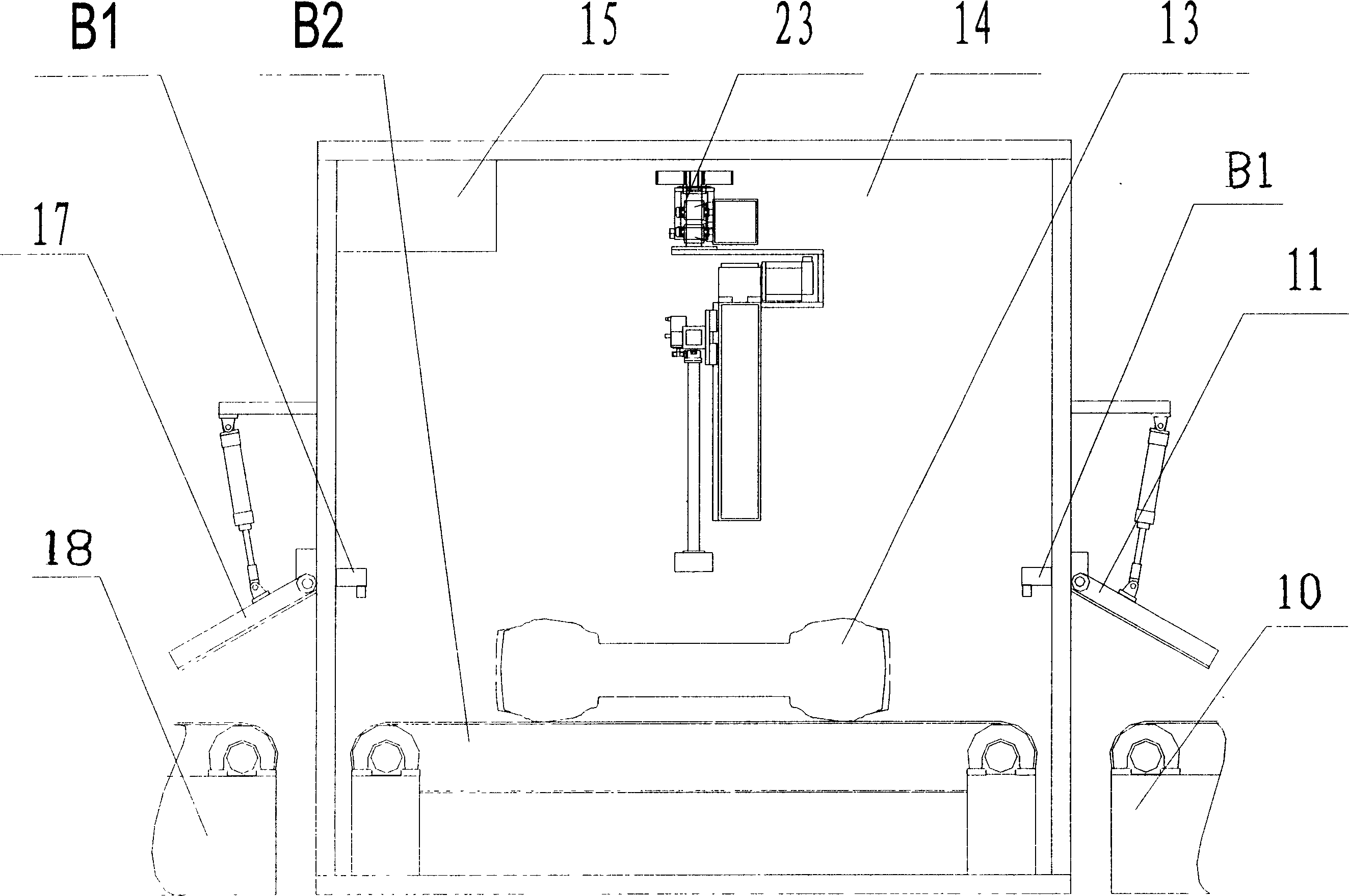
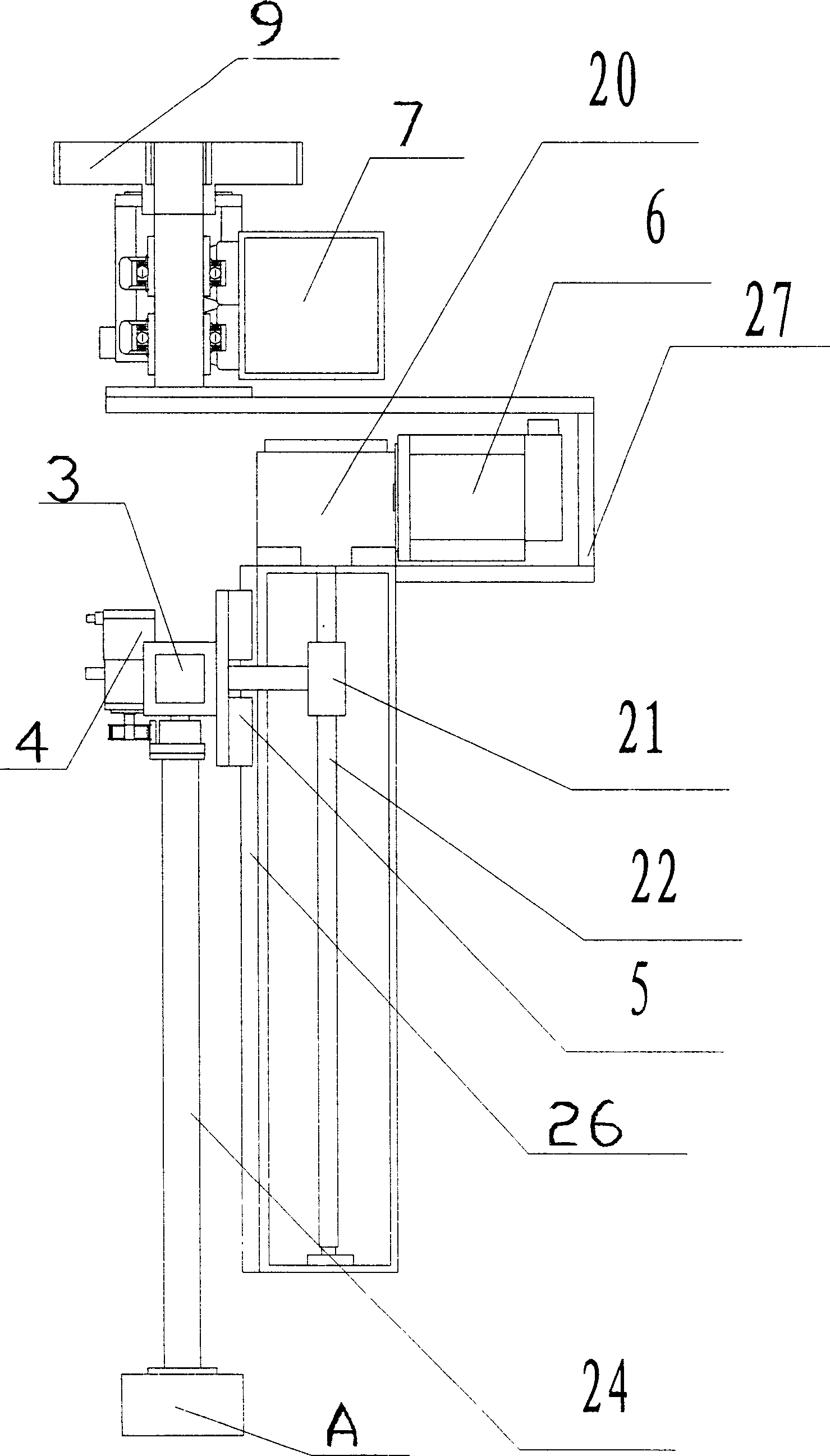
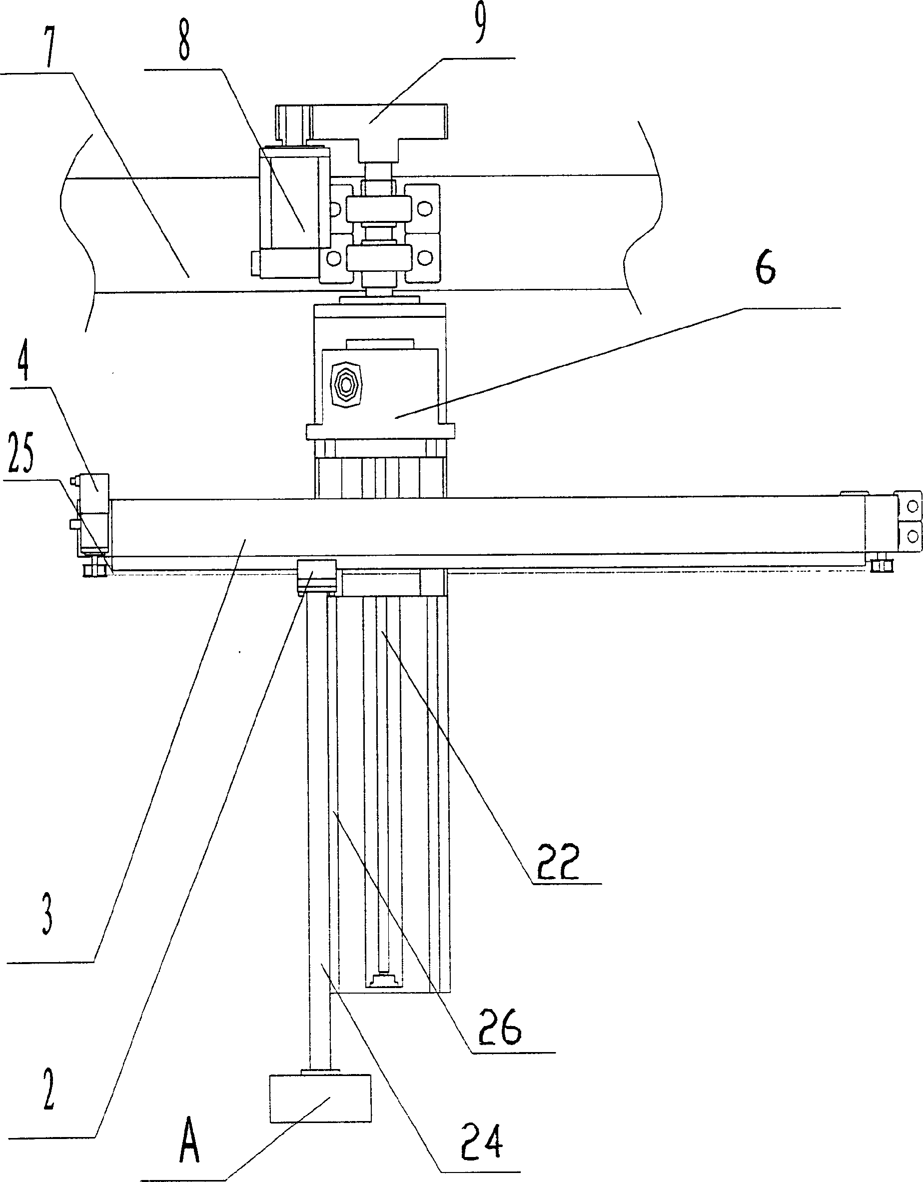
[0030] Such as figure 1 , figure 2 , image 3 As shown, the laser speckle tire nondestructive tester of the present invention includes a detection chamber 14, a vacuum device 15, a main beam 7, a detection head movement mechanism 23, an automatic tire positioning device B, a tire inlet door 11 and a tire outlet door 17; and a detection head The movement structure 23 includes a laser speckle detection head A, a detection head connecting rod 24, a rotation movement mechanism, a vertical movement mechanism, and a horizontal movement mechanism. The rotation movement mechanism includes a rotation drive motor 8, a rotation gear 9, and a rotation connector 27; a horizontal movement mechanism Including horizontal moving linear bearing pair 2, horizontal moving beam 3, horizontal moving drive motor 4; vertical moving mechanism including vertical moving linear bearing pair 5, vertical moving drive motor 6, vertical moving slide 26; detection head moving mechanism 23 through the main beam 7...
Embodiment 2
[0032] This embodiment illustrates the structure of the tire entrance and exit doors. The specific structures of the tire inlet door 11 and the tire outlet door 17 of the present invention are as follows Figure 4 As shown, the tire inlet door 11 and the tire outlet door 17 have the same structure, including a fixed plate 42, a cylinder 36, a door plate 40, a sealing rubber 41, a connecting head 35, a connecting head 39, a connecting fixed block 37, and a rotating shaft 38. The cylinder 36 is connected by The head 35 and the connecting head 39 are connected to the fixed plate 42 and the door plate 40. There is a sealing rubber on the edge of the door plate. The door plate 40 is connected to the detection chamber 14 through the connecting fixed block 37 and the rotating shaft 38.
[0033] When the tire 13 enters the detection chamber 14, the computer-controlled cylinder 36 contracts, the door panel 40 opens, and the tire inlet door 11 opens; when the tire 13 enters the detection ch...
Embodiment 3
[0035] This embodiment illustrates the structure of the tyre in and out conveyor belt mechanism. The specific structures of the tire inlet conveyor belt 10 and the tire outlet conveyor belt 18 of the present invention are as follows: Figure 5 As shown, the tire inlet conveyor belt 10 and the tire outlet conveyor belt 18 have the same structure, including a roller 28, a motor 29 and a reducer 30, a conveyor belt 31, and a bracket 32. The motor 29 is connected to the reducer 30, and the roller 28 is connected to the conveyor belt 31. , The motor 29 drives the reducer 30, and the reducer 30 drives the roller 28 to drive the conveyor belt 31. The reducer 30 drives the roller 28 to drive the conveyor belt 31. The power transmission of the reducer 30 drives the roller 28. Sprockets and chains can be used, or a timing belt can be used.
[0036] Place the tire 13 on the conveyor belt 31 of the tire inlet conveyor belt 10, the motor 29 drives the reducer 30, the reducer 30 drives the roll...
PUM
 Abstract
Description
Claims
Application Information