
A phase-lock laser frequency stabilization method

A frequency stabilization and laser technology, applied in lasers, laser parts, optics, etc., can solve the problems that frequency stabilization method cannot obtain additional modulation of frequency and intensity, and the stable point of frequency is prone to drift.

Inactive Publication Date: 2005-06-29
WUHAN INST OF PHYSICS & MATHEMATICS CHINESE ACADEMY OF SCI
View PDF0 Cites 14 Cited by
  • Summary
  • Abstract
  • Description
  • Claims
  • Application Information

AI Technical Summary

Problems solved by technology

The advantage of differential frequency stabilization is that there is no additional modulation of laser frequency and intensity, and its disadvantage is that the frequency stabilization circuit is in a DC working state, and the stable point of frequency is prone to drift
The advantage of phase-locked frequency stabilization is that the frequency center can be locked on the peak point of the frequency-stabilized reference source without drift. The disadvantage is that the introduction of modulation causes additional modulation of the laser frequency, and is usually accompanied by a change in laser intensity. Additional modulation
[0005] In short, the existing frequency stabilization methods cannot obtain the effect of laser frequency stabilization without additional modulation of frequency and intensity, and without drift

Method used


Image

  • A phase-lock laser frequency stabilization method
  • A phase-lock laser frequency stabilization method
  • A phase-lock laser frequency stabilization method

Examples


Embodiment Construction

[0021] The present invention will be further described below in conjunction with accompanying drawing:

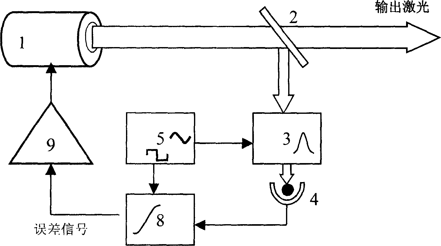
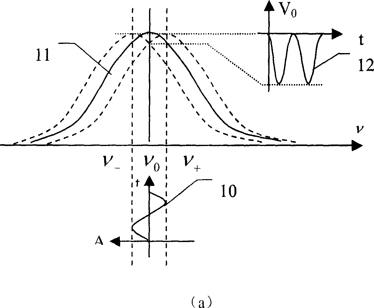
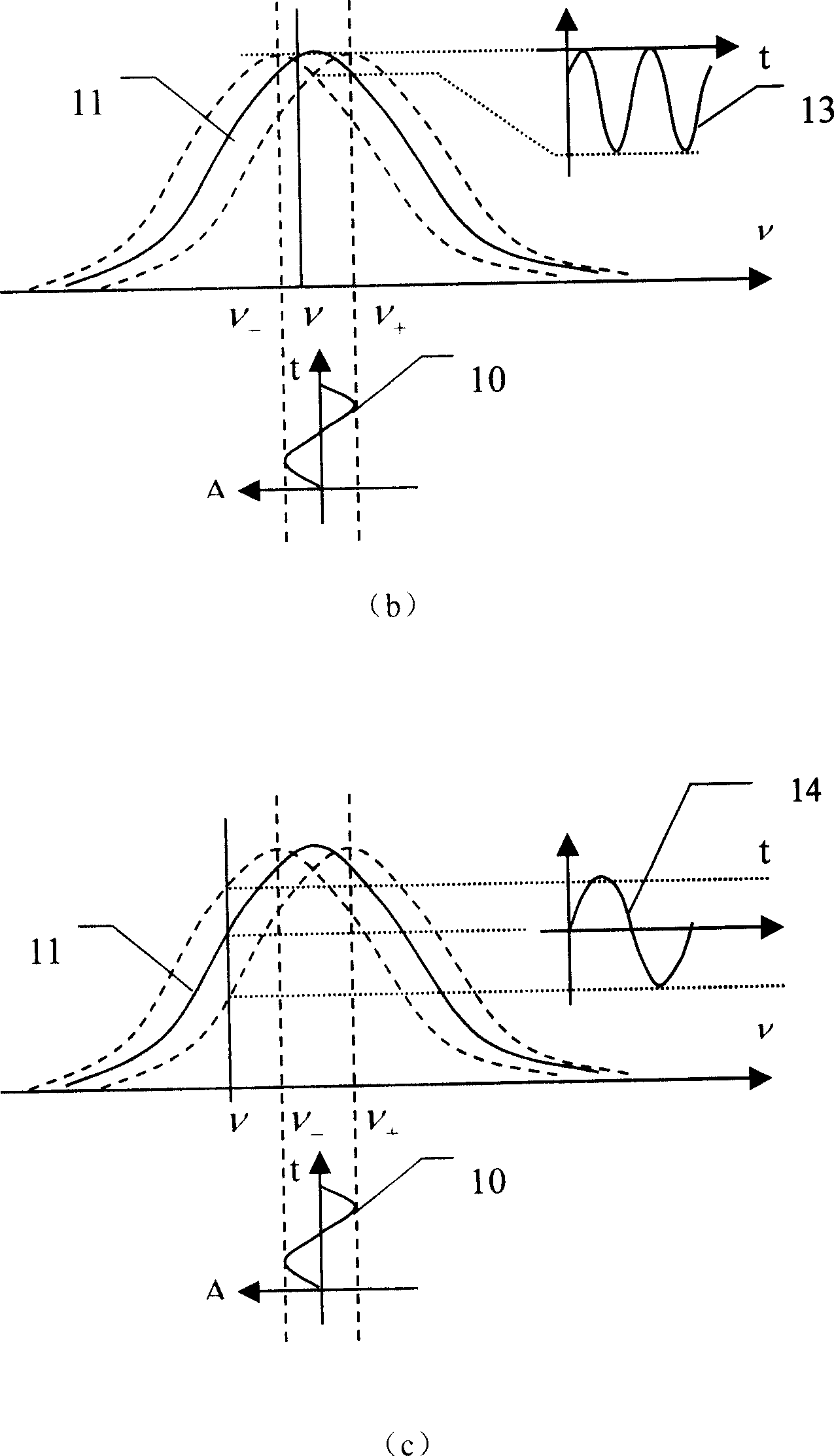
[0022] Structure of the present invention is: as figure 1 As shown, a beam splitter 2 is placed on the output optical path of the tunable laser 1, and a frequency stabilization reference source 3 and a photodetector 4 are coaxially placed in sequence on the reflection optical path of the beam splitter 2, and the output electrical signal of the photodetector 4 Sent to the phase-sensitive detector 8; the sine wave signal output by the modulation signal source 5 is applied to the frequency stabilization reference source 3; the square wave signal output by the modulation signal source 5 is sent to the phase-sensitive detector 8, and the output of the phase-sensitive detector 8 The error signal is sent to a tuning driver 9 whose output signal is applied to the tunable laser 1 .

[0023] Describe working process of the present invention below in conjunction with accompanying dra...


PUM


Abstract

This invention discloses a phase-locking laser frequency stabilizing method realized by a phase-locking laser frequency stabilizing device composed of a tunable laser, a beam splitter, a frequency stabilized primary standard source, a photoelectric detector, a modulated signal source, a phase-sensitive wave detector and a tunable drive, characterizing in applying the modulated signal output by its source onto the frequency stabilized primary standard source to lock the laser frequency on a target frequency point the output laser has no frequency shift.

Description

Technical field: [0001] The invention relates to laser frequency stabilization, in particular to a phase-locked laser frequency stabilization. Background technique: [0002] The current laser frequency stabilization methods can be divided into differential frequency stabilization and phase-locked frequency stabilization. [0003] The method of differential frequency stabilization is: let the output frequency of the laser be located on the slope of the frequency stabilization reference source (absorption peak slope, transmission peak slope, etc.), separate two beams from the output laser, and one of the laser beams is identified by the frequency stabilization reference source. Frequency, get the outgoing laser intensity I 1 , adjust the intensity I of another laser beam 2 , making it close to I 1 , with I 1 and I 2 The difference is used as an error signal, and the negative feedback locks the output frequency of the laser. The advantage of differential frequency stabili...

Claims


Application Information

Patent Timeline
Patent Type & Authority Applications(China)
IPC IPC(8): G02F1/35H01S3/13
Inventor 李发泉王玉平程学武高克林龚顺生
Owner WUHAN INST OF PHYSICS & MATHEMATICS CHINESE ACADEMY OF SCI
Learn More