

Low-temperature polarizing electronic Raman scattering apparatus
A Raman scattering, low temperature technology, applied in the field of optics
- Summary
- Abstract
- Description
- Claims
- Application Information
AI Technical Summary
Problems solved by technology
Method used
Image

Examples
Embodiment Construction
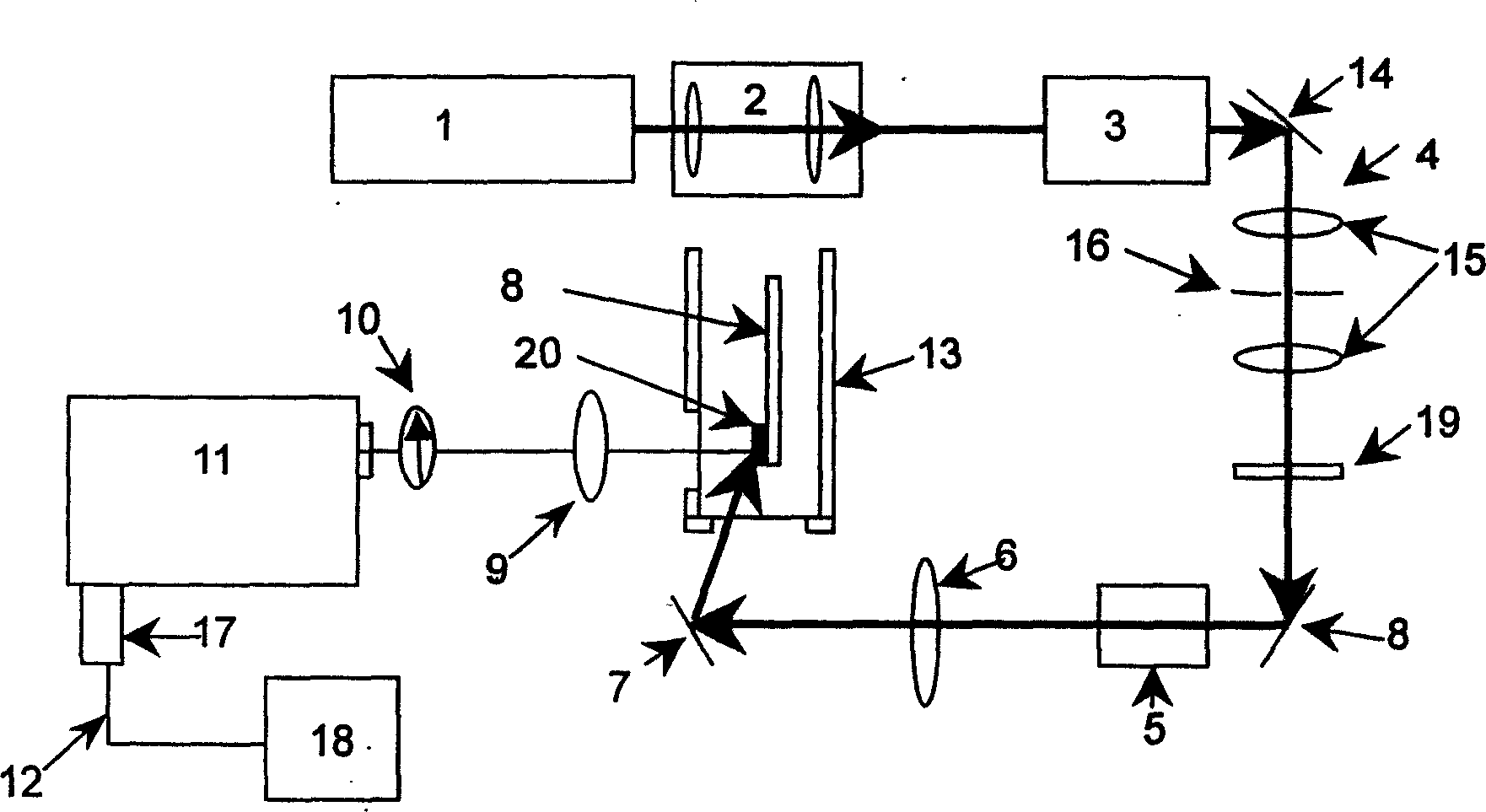
[0015] A low-temperature polarized electron Raman scattering device according to the present invention, such as figure 1 shown. Among them: 1 is the argon ion laser, 2 is the collimating lens group, 3 is the plasma line filter, 4 is the spatial filter, 5 is the polarization rotator, 6 is the focusing lens, 7 is the mirror, 8 is the sample holder, 9 is the objective lens, 10 is the polarizer, 11 is the spectrometer, 12 is the monitor, 13 is the liquid helium cryostat, 14 is the plane mirror, 15 is the lens, 16 is the pinhole, 17 is the detector, 18 is the computer, 19 is Neutral density filter, 20 is a sample.
[0016] Argon ion laser 1 uses green light at 514nm. The laser light first enters a collimating lens group 2, which can be used to reduce the divergence of the laser light generated by the laser. The collimated laser light enters the plasma line filter 3, because the exiting laser also contains plasma lines of other wavelengths. The plasma filter is to ensure better m...
PUM
 Abstract
Description
Claims
Application Information