

Manufacturing method of die cutting roller, press cutting roller or indentation roller
A manufacturing method and technology of die-cutting rollers, which are applied in the direction of manufacturing tools, coatings, laser welding equipment, etc., can solve problems such as process parameters, and achieve the effects of reducing material costs and solving air holes and cracks
- Summary
- Abstract
- Description
- Claims
- Application Information
AI Technical Summary
Problems solved by technology
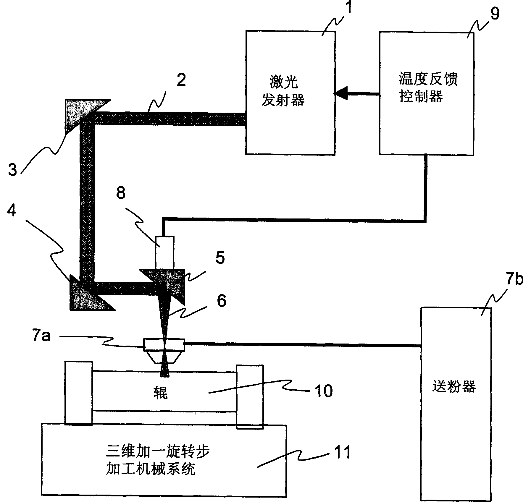
Method used
Image

Examples
Embodiment 1
[0028] Embodiment 1, pressure cutting roll: low-cost high-carbon alloy steel roll φ9.9 inches × 32 inches;
[0029] The weight percentage of the main components of the material used in the temperature-controlled laser surface metallurgical powder coating:
[0030] Vanadium V Carbon C Manganese Mn Silicon Si Chromium Cr Molybdenum Mo Sulfur S Iron Fe and impurities
[0031] High vanadium alloy steel A 7% 1.6% 0.7% 1.0% 5.95% 2.3% 0 80.45%
[0032] The process parameters of high vanadium alloy steel metallurgical powder coating on temperature-controlled laser surface are:
[0033] Coating surface temperature setting 2200℃±50℃
[0034] Laser output power 2.5kw~6.0kw
[0035] Laser spot diameter 4mm
[0036] 40mm from focal length
[0037] Laser circular spot scanning line speed 4mm / s
[0038] Powder coating powder feeding rate 12g / min
[0039] WEDM burns 1 cubic inch of steel per hour, maintaining edge dimensions to an accuracy of ±0.001 inches.
Embodiment 2
[0040] Embodiment 2, pressure cutting roll: low-cost medium carbon alloy steel roll φ10 inches × 24 inches;
[0041] The weight percentage of the main components of the material used in the temperature-controlled laser surface metallurgical powder coating:
[0042] Vanadium V Carbon C Manganese Mn Silicon Si Chromium Cr Molybdenum Mo Sulfur S Iron Fe
[0043] High vanadium alloy steel C 16.3% 3.4% 0.5% 0.8% 5.25% 1.7% 0.08% 71.97%
[0044] The process parameters of high vanadium alloy steel metallurgical powder coating on temperature-controlled laser surface are:
[0045] Coating surface temperature setting 1700℃±50℃
[0046] Laser output power 2.5kw~6.0kw
[0047] Laser spot diameter 6mm
[0048] 50mm from focal length
[0049] Laser circular spot scanning line speed 2mm / s
[0050] Powder coating powder feeding rate 8g / min
[0051] EDM burns away 1 cubic inch of steel per hour, maintaining edge dimensions to an accuracy of ±0.001 inches.
Embodiment 3
[0052] Embodiment 3, die-cutting belt creasing roll: low-cost low-carbon steel roll φ17 inches × 48 inches; temperature-controlled laser surface metallurgy powder coating The main component weight percentage of the material used:
[0053] Vanadium V Carbon C Manganese Mn Silicon Si Chromium Cr Molybdenum Mo Sulfur S Iron Fe
[0054] High vanadium alloy steel B 9.5% 2.7% 0.3% 1.0% 5.35% 2.1% 0.1% 78.95%
[0055] The process parameters of high vanadium alloy steel metallurgical powder coating on temperature-controlled laser surface are:
[0056] Coating surface temperature setting 2000℃±50℃
[0057] Laser output power 1.5kw~6.0kw
[0058] Laser spot diameter 5mm
[0059] 38mm from focal length
[0060] Laser circular spot scanning line speed 16mm / s
[0061] Powder coating powder feeding rate 14g / min
[0062] WEDM burns 1 cubic inch of steel per hour, maintaining edge dimensions to an accuracy of ±0.001 inches.
[0063] For medium and large die-cutting rolls, p...
PUM
 Abstract
Description
Claims
Application Information