Rotating cage type floating stuffing biological sewage treatment method and equipment thereof

The technology of a sewage treatment device and sewage treatment method, which is applied in the field of water treatment, can solve the problems of energy consumption, lack of leaves, and low aeration efficiency, and achieve the effects of low operating cost, uniform flow state, and accelerated shedding

Inactive Publication Date: 2005-08-17
SOUTH CHINA UNIV OF TECH
View PDF2 Cites 18 Cited by
  • Summary
  • Abstract
  • Description
  • Claims
  • Application Information

AI Technical Summary

Problems solved by technology

But there are still some shortcomings. 1. The aeration efficiency is low by relying on the drum (drum) to turn out of the water surface and contact with the air; 2. The drum (drum) works in a semi-immersion mode, and the contact amount between the biofilm and the sewage is limited. , and the processing efficiency is also limited accordingly; 3. There are no blades on the outer periphery, which needs to be driven by a driving device, which consumes energy
[0003] The Chinese patent application with applic

Method used


Image

  • Rotating cage type floating stuffing biological sewage treatment method and equipment thereof
  • Rotating cage type floating stuffing biological sewage treatment method and equipment thereof
  • Rotating cage type floating stuffing biological sewage treatment method and equipment thereof

Examples


Embodiment 1

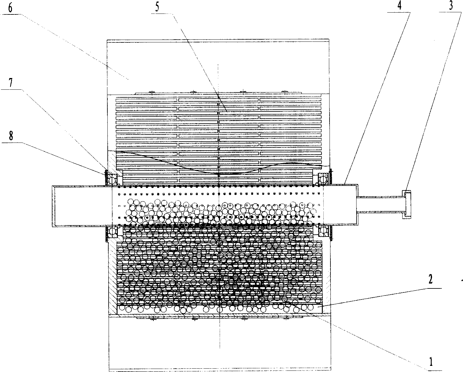
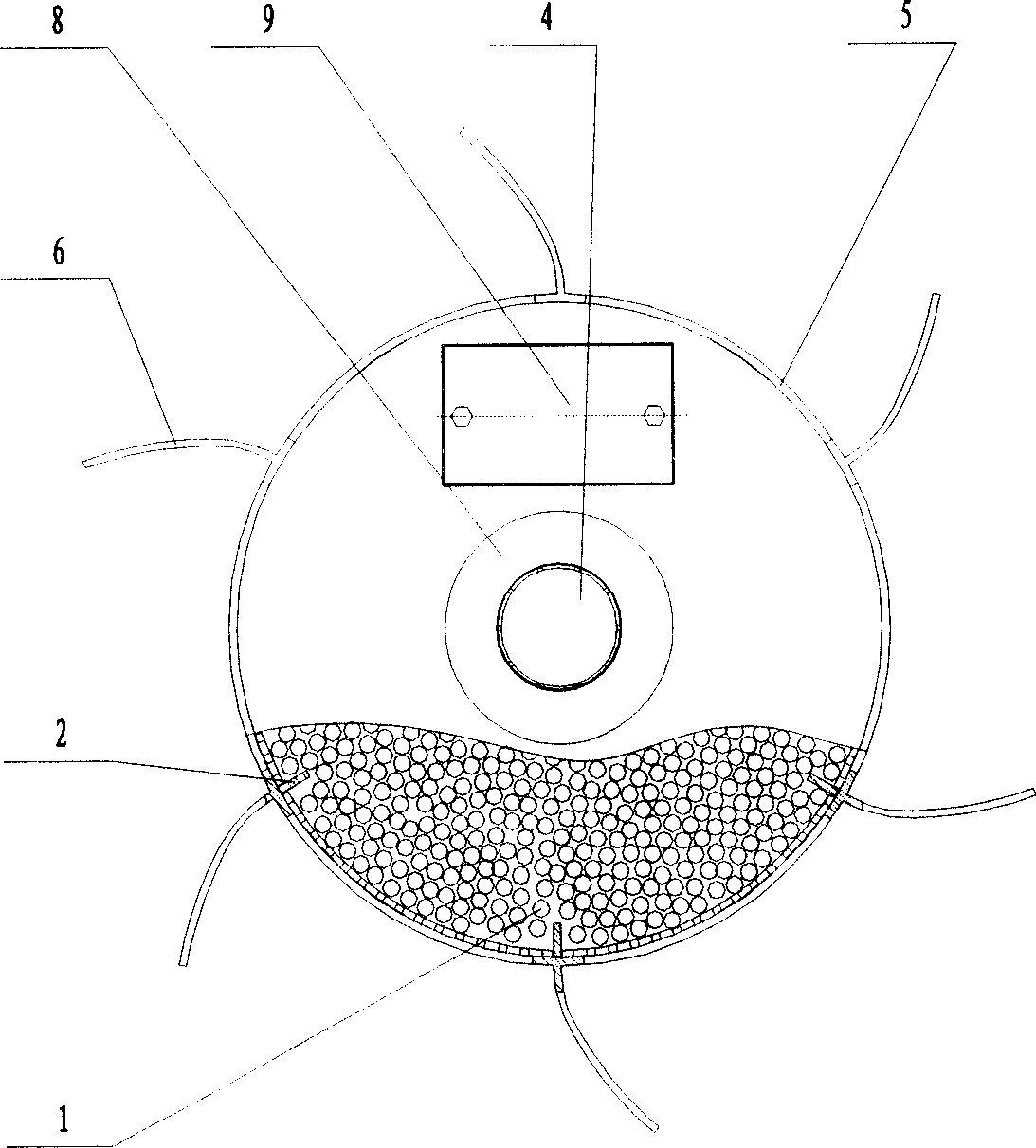
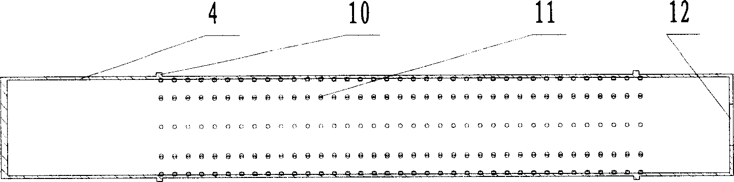
[0034] Such as figure 1 , figure 2 As shown, the rotating cage type suspended packing biological sewage treatment device consists of suspended packing 1, inner blade 2, aeration inlet pipe 3, central shaft 4, rotating cage body 5, outer blade 6, bearing 7, bearing cover plate 8, feeding window cover Plate 9 composition. Central axis 4 such as image 3 As shown, there is a shaft shoulder 10 of the axial positioning bearing on the peripheral curved surface, and there are micropores 11 with a porosity of 47%; one end of the central shaft 4 is closed, and an air inlet 12 is left at the other end. The aeration inlet pipe 3 is fixed; the central shaft 4 is connected with the rotating cage body 5 through a bearing 7, and the bearing 7 is positioned by a bearing cover plate 8 and screws. Rotating cage body 5 such as Figure 4 As shown, there is a water inlet hole 13 on its peripheral curved surface. The present embodiment is a square hole with an opening rate of 85%. There is a f...

Embodiment 2

[0037] In the present embodiment, the opening ratio of the micropores on the peripheral curved surface of the central axis 4 is 52%; the peripheral curved surface of the rotating cage body 5 is provided with water inlet holes 13, which are circular or oval holes, and the aperture ratio is 78%. . Suspended filler 1 is made of plastic suspended filler, and its filling rate is 46% of the volume of the tumbler cage. Outer blade 6 as Figure 8The V-shaped plane shown has a height of 0.35 times of the radius of the rotating cage body 5 . The inner blade 2 is a curved surface, and the height is 0.3 times of the radius of the rotating cage body 5. The inner and outer blades are integrated into one body and connected with the rotating cage body by bolts. The number of the outer blades and the inner blades is 8. All the other implementations are the same as in Example 1.


PUM


Abstract

The present invention relates to water treating technology, and is especially one kind of rotary cage type biological suspended stuffing sewage treating method and apparatus. The apparatus includes central shaft, rotary cage, inner and outer vanes, suspended stuffing, bearing and bearing cover plate. The central shaft is connected to the rotary cage to form rotating pair, the bearing is located with the bearing cover plate and screws, the suspended stuffing is filled into the rotary cage, and the inner and outer vanes are screwed to peripheral wall of the rotary cage. The inflowing sewage drives the outer vanes to rotate the rotary cage and mixes with the suspended stuffing and central aerating airflow, the inner vanes of the rotary cage form homogeneous gas, liquid and solid fluid to make sewage well contact with biological membrane on the stuffing and aerating airflow for biodegradation and airflow oxidation decomposition of organic pollutant and purification of sewage.

Description

technical field [0001] The invention relates to water treatment technology, in particular to a method and device for treating biological sewage with a tumbler type suspended filler. Background technique [0002] The biological turntable is one of the important devices for the biological treatment of sewage, but the traditional biological turntable technology has some shortcomings in practical application, such as the small specific surface area of ​​the disk and low treatment efficiency. The Chinese patent No. 97242354.0 discloses a kind of sewage treatment device with a biological drum (drum) of filler, which improves the traditional biological drum and adopts a biological drum (drum) structure with filler in it. Processing efficiency, manufacturing and other aspects have been greatly improved. But there are still some shortcomings. 1. The aeration efficiency is low by relying on the drum (drum) to turn out of the water surface and contact with th...

Claims


Application Information

Patent Timeline
IPC IPC(8): C02F3/10
CPCY02W10/10
Inventor 陈维平江帆吴纯德朱权利张弢张文
Owner SOUTH CHINA UNIV OF TECH
Why Eureka
Try Eureka