

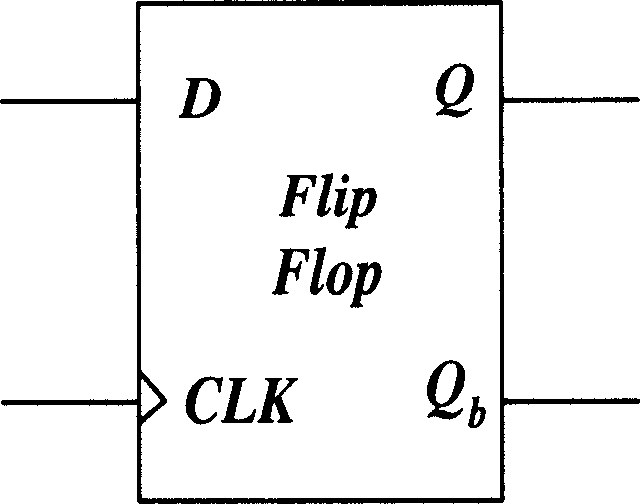
High-speed low clock signal oscillation amplitude driving conditional precharging CMOS trigger
A clock signal and flip-flop technology, applied in electrical components, pulse generation, electrical pulse generation, etc., can solve the problems of increasing the capacitance of the internal nodes of the circuit, increasing the power consumption of the circuit, limiting the working speed of the circuit, etc., to achieve a small circuit area, The circuit area is relatively small and the effect of saving power consumption
- Summary
- Abstract
- Description
- Claims
- Application Information
AI Technical Summary
Problems solved by technology
Method used
Image

Examples
Embodiment Construction
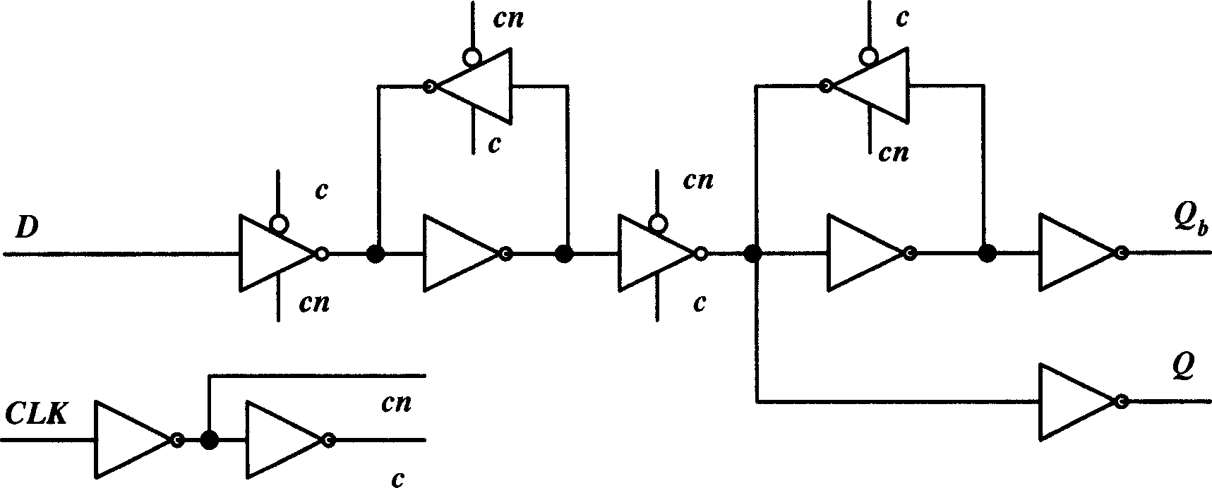
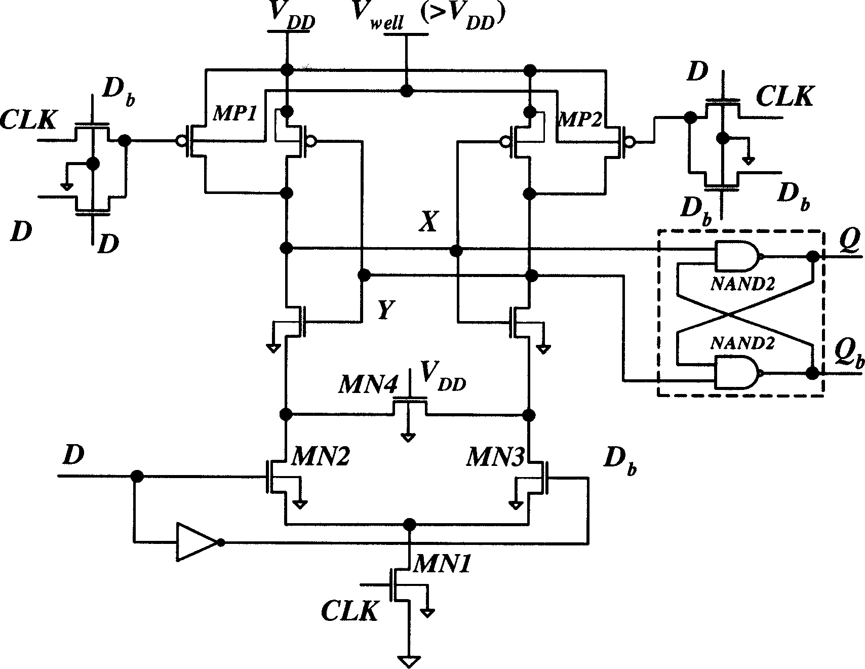
[0024] The technical scheme that the present invention solves its technical problem is: the high-speed low clock signal swing condition precharge flip-flop SAFF_CP_SFL that the present invention proposes, as Figure 5 Show. The SAFF_CP_SFL flip-flop also has the characteristics of being driven by a low-swing clock signal and using conditional precharge technology to reduce the power consumption of the flip-flop circuit itself, and because the complementary output terminals of the first-stage latch are respectively connected to two independent parallel On a single-clock phase latch with the same circuit parameters, the complementary outputs Q and Q of the SAFF_CP_SFL flip-flop can be guaranteed b Both can realize symmetrical rising edge delay and falling edge delay. Compared with the SAFF_CP flip-flop circuit, the structure of the SAFF_CP_SFL flip-flop circuit is simpler, reducing an additional high-voltage power supply line V well (Provide substrate bias for PMOS transistors...
PUM
 Abstract
Description
Claims
Application Information