
Organic eletroluminesence element

An electroluminescence element and electroluminescence technology, applied in the direction of electroluminescence light source, electrical element, electric light source, etc., can solve the problems of inability to achieve life, organic EL element not yet developed, long efficiency and so on

Inactive Publication Date: 2005-10-05
SANYO ELECTRIC CO LTD
View PDF1 Cites 14 Cited by
  • Summary
  • Abstract
  • Description
  • Claims
  • Application Information

AI Technical Summary

Problems solved by technology

[0012] However, in the above-mentioned conventional methods, an organic EL element with a sufficiently long life and a sufficiently high efficiency cannot be obtained.
In particular, an organic EL element that has a long life and high efficiency and emits blue light cannot be realized
That is, organic EL elements that can emit the luminous colors of R (red), G (green), and B (blue) that satisfy the luminous efficiency and lifespan required for full-color display have not yet been developed.

Method used


Image

  • Organic eletroluminesence element
  • Organic eletroluminesence element
  • Organic eletroluminesence element

Examples


Embodiment

[0118] [Example]

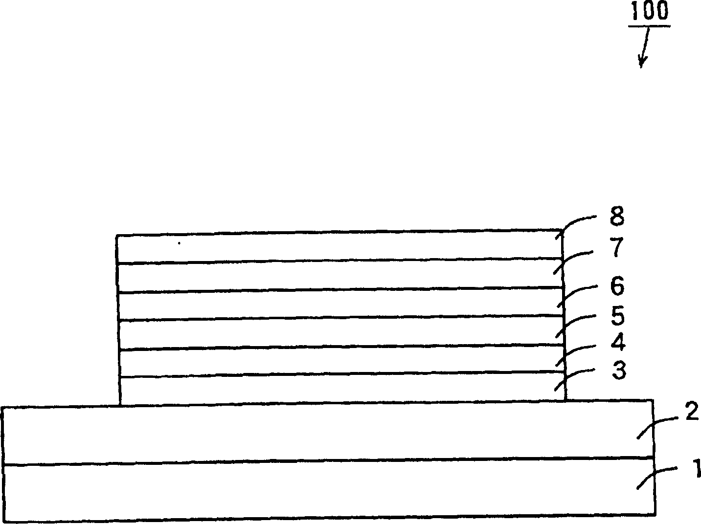
[0119] The structure of the organic EL element of this example is the same as that of the organic EL element 100 of the above-mentioned embodiment.

[0120] In this example, a driving voltage was applied between the hole injection electrode 2 and the electron injection electrode 8 of the organic EL element 100, and the luminous efficiency and lifetime of the organic EL element 100 were measured. In addition, the lifetime means the time until the luminance value of the organic EL element 100 decreases to 1 / 2 of the initial value.

[0121] The luminescent color of the organic EL element 100 is blue, the luminous efficiency is 11 cd / A, and the lifetime is 150 hours.


PUM


Abstract

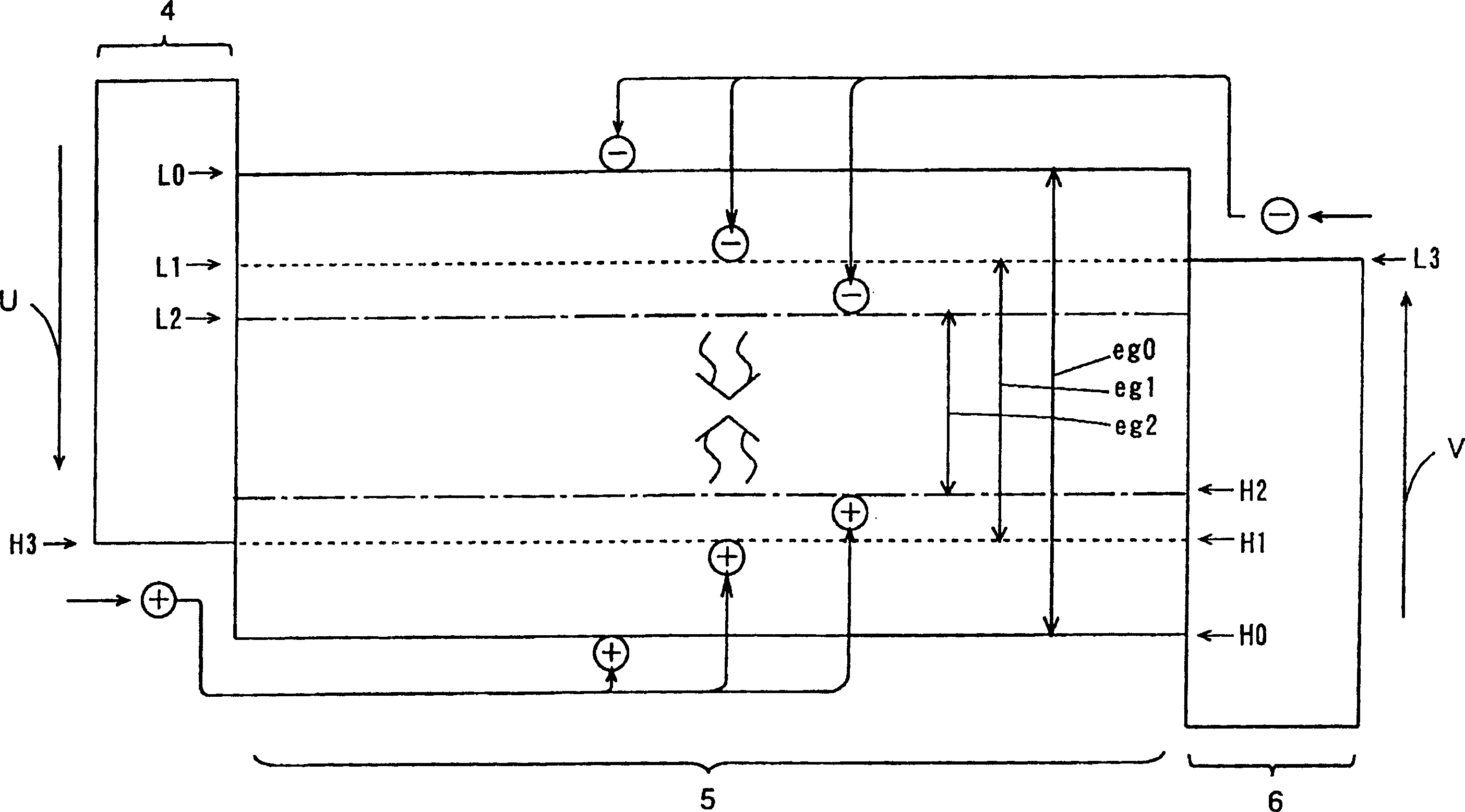
A hole injection electrode made of a transparent conductive film is formed on a substrate made of indium-tin oxide (ITO) or the like. On the hole injection electrode, a hole injection layer, a hole transport layer, a light emitting layer, an electron transport layer, and an electron injection layer are formed in order. On the electron injection layer, an electron injection electrode made of aluminum is formed. The light emitting layer includes a first dopant made of a material capable of converting triplet excitation energy to an emission of a predetermined color and a second dopant made of a material capable of converting single excitation energy to an emission of the same color as the predetermined color. The difference between the emission peak wavelength of the first dopant and the emission peak wavelength of the second dopant is preferably 20 nm or less.

Description

technical field [0001] The present invention relates to organic electroluminescent elements. Background technique [0002] Organic electroluminescent elements (hereinafter referred to as organic EL elements) are expected to become new self-luminous elements. An organic EL element has a laminated structure in which a hole transport layer, a light emitting layer, and an electron transport layer are sequentially formed between a hole injection electrode and an electron injection electrode. [0003] An electrode material having a large work function such as gold or indium-tin oxide (ITO) is used as the hole injecting electrode, and an electrode material having a small work function such as magnesium or lithium is used as the electron injecting electrode. [0004] By applying a voltage between the hole injection electrode and the electron injection electrode of the organic EL element, holes are injected from the hole injection electrode and electrons are injected from the electr...

Claims


Application Information

Patent Timeline
Patent Type & Authority Applications(China)
IPC IPC(8): C09K11/06H05B33/14H05B33/20H10K99/00
CPCH01L51/0073H01L51/0065C09K2211/185H01L51/0085C09K2211/1037H01L51/0058C09K2211/1029H01L51/5016H01L51/0087H01L51/0071C09K2211/1092H01L51/0061H01L51/0072H01L51/0054H01L51/5012C09K11/06H05B33/14H10K85/653H10K85/622H10K85/636H10K85/626H10K85/657H10K85/6574H10K85/346H10K85/342H10K85/6572H10K50/11H10K2101/10
Inventor 松末哲征
Owner SANYO ELECTRIC CO LTD
Learn More