Method of generating hydrogen gas, hydrogen gas production apparatus and energy conversion system

An energy conversion system, hydrogen technology, applied in chemical instruments and methods, hydrogen, electrical components, etc., can solve problems such as hindering continuous use, restriction, hydrogen pollution, etc., and achieve the effect of improving reliability

Inactive Publication Date: 2005-10-05
SONY CORP
View PDF3 Cites 5 Cited by
  • Summary
  • Abstract
  • Description
  • Claims
  • Application Information

AI Technical Summary

Problems solved by technology

This limits the choice of initial composition of the solution and prevents continuous use of a solution of ideal composition
[0019] Another problem involved in the above reaction system is that hydrogen gas is directly generated from the alkaline aqueous solution, so the generated hydrogen gas is inevitably polluted by moisture (mist) containing impurities such as sodium hydroxide
These pollutants not only limit the choice of materials for the reaction system, but also degrade the characteristics of the reaction system.

Method used


Image

  • Method of generating hydrogen gas, hydrogen gas production apparatus and energy conversion system
  • Method of generating hydrogen gas, hydrogen gas production apparatus and energy conversion system
  • Method of generating hydrogen gas, hydrogen gas production apparatus and energy conversion system

Examples


Embodiment approach 1

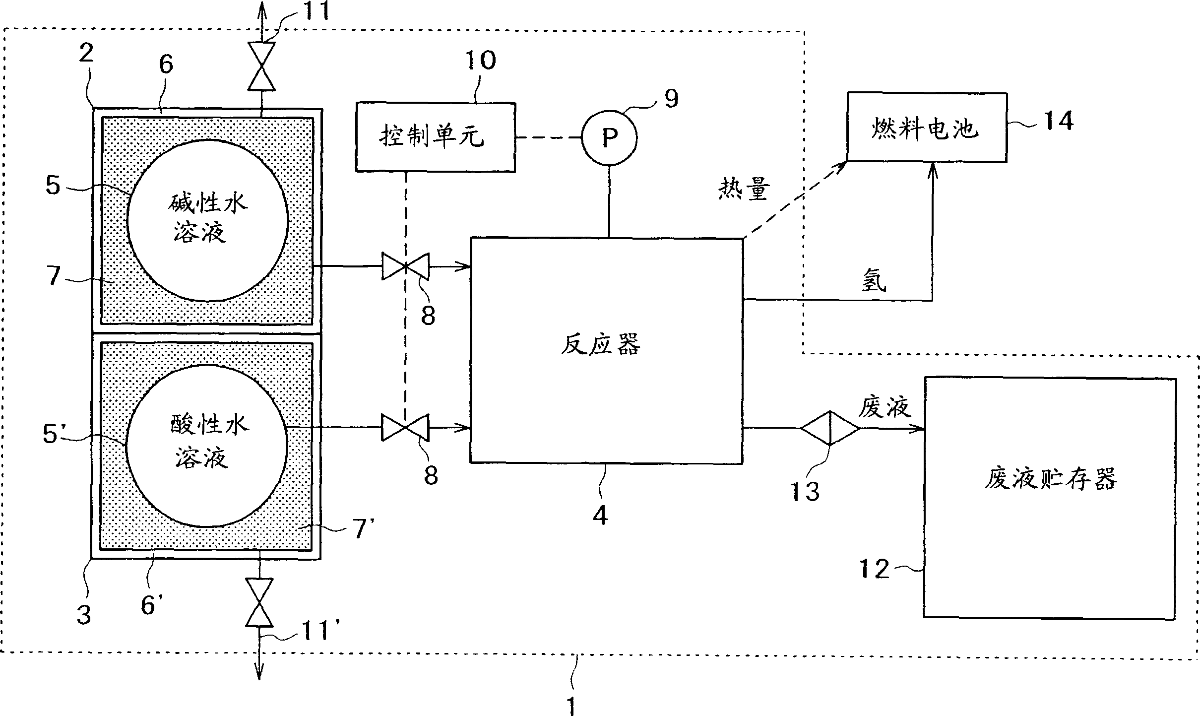
[0053] figure 1 is a schematic diagram showing the apparatus of the present invention for generating hydrogen.

[0054] Such as figure 1 As shown, the device 1 for generating hydrogen of the present invention is composed of a first storage tank 2 for storing an alkaline aqueous solution of a metal hydride, a second storage tank 3 for storing an acidic aqueous solution as a second solution, and a reactor 4. In the reactor A basic aqueous solution and an acidic aqueous solution are mixed together for a reaction in which hydrogen gas is released. The first reservoir 2 and the second reservoir 3 are connected to the reactor 4 .

[0055] Between the first and second reservoirs 2 and 3 and the reactor 4 there is a flow regulator 8 . The reactor 4 is equipped with a pressure sensor 9 that detects the flow rate and a control unit 10 that controls the flow rate regulator 8 in response to the pressure detected by the pressure sensor 9 .

[0056] The device 1 for generating hydrogen ...

Embodiment approach 2

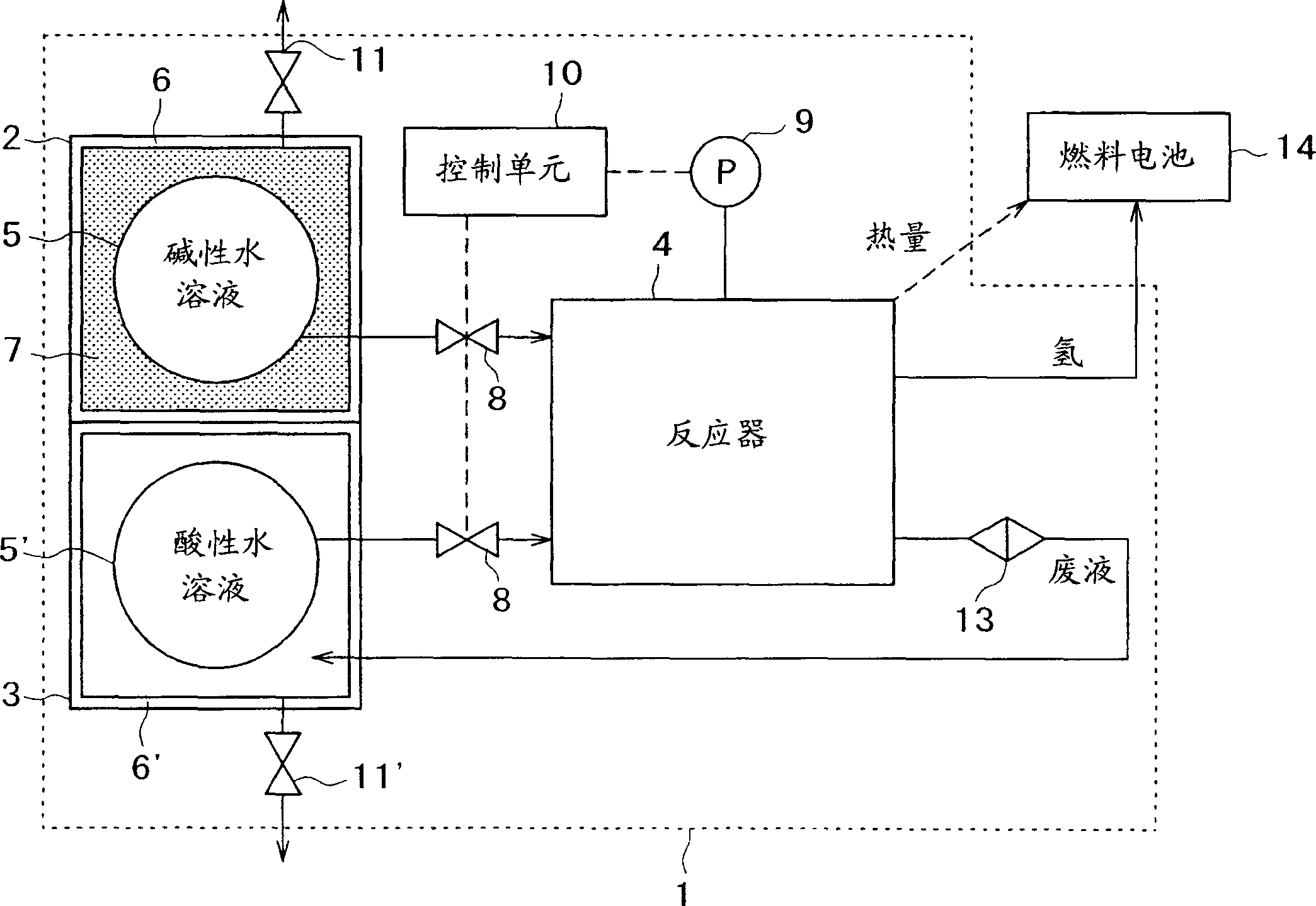
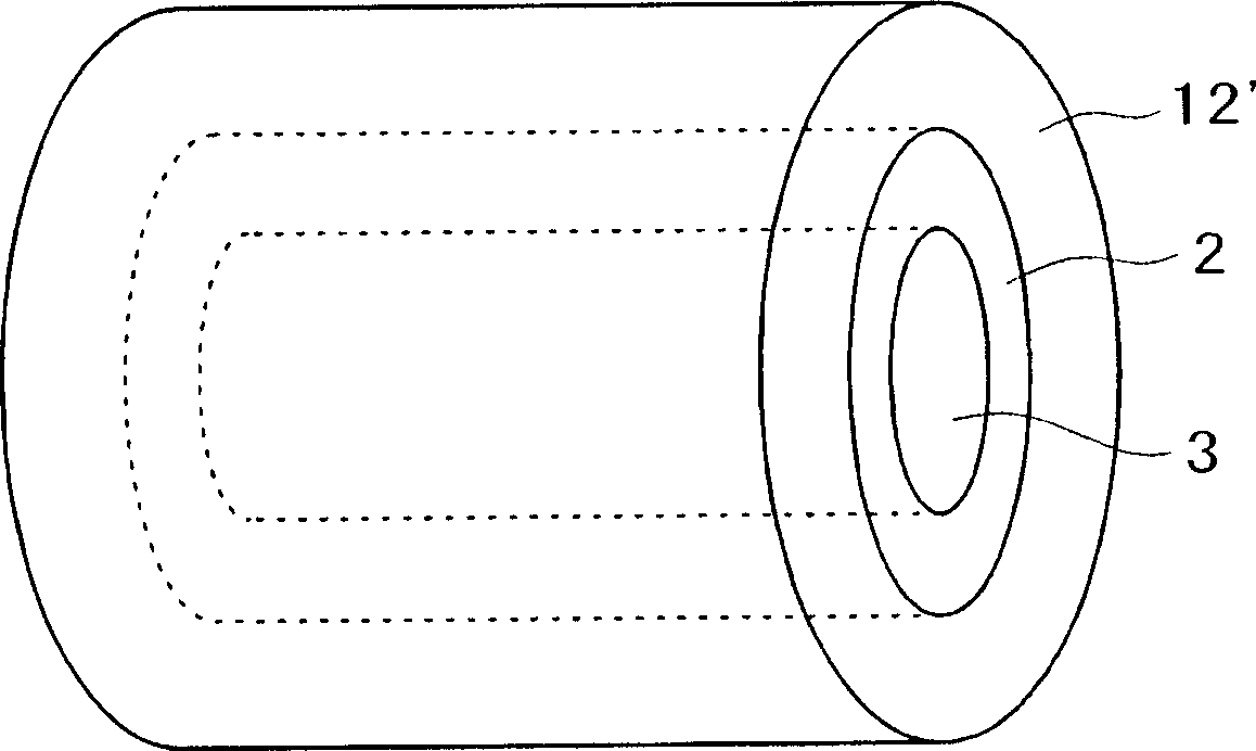
[0072] The device for generating hydrogen according to Embodiment 2 of the present invention such as image 3 and 4 shown. It has a first reservoir 2 for storing an alkaline aqueous solution of a metal hydride and a second reservoir 3 for storing an acidic aqueous solution as a second solution, which are concentric double (or multi) tube structures. Reservoirs 2 and 3 can be connected to reactor 4 . In this case, as image 3 and 4 As shown, the waste liquid reservoir 12' is installed coaxially on the outside of the second reservoir 2, although it can be as figure 1 shown installed separately.

[0073] A syringe-type structure is applicable to the first reservoir 2, the second reservoir 3, and the waste liquid reservoir 12'. In this case, the first and second reservoirs 2 and 3 are equipped with movable walls 15 to push out the alkaline and acidic aqueous solutions. The movable wall 15 is urged in one direction by elastic means 16 (eg a spring). In other words, it acts ...

Embodiment approach 3

[0080] The method of generating hydrogen of the present invention is based on a liquid phase reaction. The hydrogen gas thus produced can entrain droplets (or moisture) of the aqueous solution. Such entrainment not only limits the choice of device materials, but also degrades the properties.

[0081] Therefore, it is required to modify the hydrogen generating apparatus 1 of the present invention so that the reactor 4 is equipped with a mechanism for separating only hydrogen.

[0082] That is to say, the reactor 4 is required to be connected with the perforated pipe 17 that can permeate hydrogen but not permeate liquid, such as Figure 5A and 5B shown. In this case, the reaction to release the hydrogen takes place in the reactor 4 and / or the porous pipe 17, so that the released hydrogen 21 and the mixture 22 (consisting of waste liquor and unreacted alkaline and acidic aqueous solutions) pass through the porous When the tube 17 is connected, only the hydrogen gas 21 passes ...


PUM


Abstract

A method of generating hydrogen gas, which can enhance the efficiency of hydrogen generation even in the absence of catalysts and can enhance reliability in repeated and long-term uses; a hydrogen gas production apparatus therefor; and an energy conversion system. A mixture system comprised of a metal hydride of the general formula: alphaz(1-x)betazx[BHy] (wherein each of alpha and beta represents an atom selected from among those of Groups 1A, 2A and 2B of the periodic table; 3 < y < 6; 0 <= x <= 1; and 0 < z < 3), water and another liquid whose pH value is lower than that of the metal hydride in the form of an aqueous solution is provided, and the metal hydride is decomposed. The apparatus comprises first storage section (2) for storing an aqueous solution of metal hydride, second storage section (3) for storing another liquid whose pH value is lower than that of the above aqueous solution, and reaction section (4) for mixing the aqueous solution with the other liquid to thereby generate hydrogen gas. The thus obtained hydrogen gas is converted to electrochemical energy by means of an energy converter.

Description

technical field [0001] The invention relates to a method for generating hydrogen, a device for generating hydrogen and an energy conversion system. Background technique [0002] Since the industrial revolution, fossil fuels such as gasoline and light oil have been widely used as energy sources in transportation, power generation and many other branches of industry. The use of fossil fuels has greatly contributed to the development of industry, which in turn has improved the standard of living of mankind. [0003] On the other hand, the earth is facing serious environmental damage problems. In addition, there are general doubts about the long-term stable supply of fossil fuels. [0004] Under these circumstances, hydrogen fuel is attracting attention as a clean energy that will soon replace fossil fuels. This is because hydrogen fuel emits only water after combustion. Efforts to develop new materials capable of efficient storage and evolution (evolution) of hydrogen gas a...

Claims


Application Information

Patent Timeline
Patent Type & Authority Applications(China)
IPC IPC(8): C01B3/06H01M8/06
CPCC01B3/065Y02E60/50Y02E60/362H01M8/065Y02E60/36C01B3/06
Inventor 守冈宏之山田淳夫须藤业猪俣浩二户木田裕一
Owner SONY CORP
Why Eureka
Try Eureka