Quick detector for photosynthetic capacity of irradiation from light emitting diode

A detection instrument and capability technology, applied in the field of photosynthesis rate measurement equipment, can solve problems such as unfavorable living body measurement, inconsistent environmental conditions, and long time consumption, so as to facilitate popularization and application, overcome measurement data errors, and avoid measurement data effect of error

Inactive Publication Date: 2005-10-26
SOUTH CHINA NORMAL UNIVERSITY
View PDF1 Cites 6 Cited by
  • Summary
  • Abstract
  • Description
  • Claims
  • Application Information

AI Technical Summary

Problems solved by technology

Therefore, it often takes a long time to measure a valid set of data
(2) Since the measurement lasts for a long time, and the external environmental state is changing all the time, the measured data is a series of random numbers, which cannot reflect the photosynthetic rate of the tested plant under the physiological conditions at that time
(3) Due to the respiration and transpiration of plant leaves during the measurement process, the environmental conditions in the leaf chamber (CO 2 Concentration, humidity, etc.) and external conditions are inconsistent, and the instrument itself cannot compensate for this difference well
(4) The price of the instrument is relatively expensive, which is not conducive to the popularization and use in agricultural production
[0003] In order to overcome the shortcomings and deficiencies of the above-mentioned equipment, the invention patent No. ZL02115395.7 applied by the applicant discloses a "photosynthetic rate measuring device for visible light-induced delayed luminescence", which has the advantages of low manufacturing cost and high measurement effect. Good advantages, but there are still the following problems: (1) Since the darkroom of its component part is a fixed structure with a large volume, and the equipment such as a microcomputer is also a relatively large-scale equipment, this device cannot be measured according to the measurement requirements. Flexible movement, the plant leaves must be picked off and placed in a darkroom for measurement, that is, in-vitro measurement, which will inevitably affect the accuracy of the measurement results. Since the in-vivo field measurement cannot be realized, the application range is relatively limited; (2 ) during the measurement process, due to structural problems, there is a time delay of 2 to 5 seconds when receiving delayed fluorescence, because the downward trend of delayed fluorescence is very fast, and most of the useful information is before 5 seconds, so this is a huge The acquisition of useful information in delayed fluorescence is greatly reduced, which greatly affects the correlation between delayed fluorescence and photosynthetic efficiency, which has a great impact on practicality; (3) using CCD or ICCD as a light receiving component, the volume itself is only It is relatively large, and it also needs liquid nitrogen cooling, which increases the volume of the whole device and makes the device less portable, which is not conducive to outdoor live body measurement, and its use is limited

Method used


Image

  • Quick detector for photosynthetic capacity of irradiation from light emitting diode
  • Quick detector for photosynthetic capacity of irradiation from light emitting diode
  • Quick detector for photosynthetic capacity of irradiation from light emitting diode

Examples


Embodiment 1

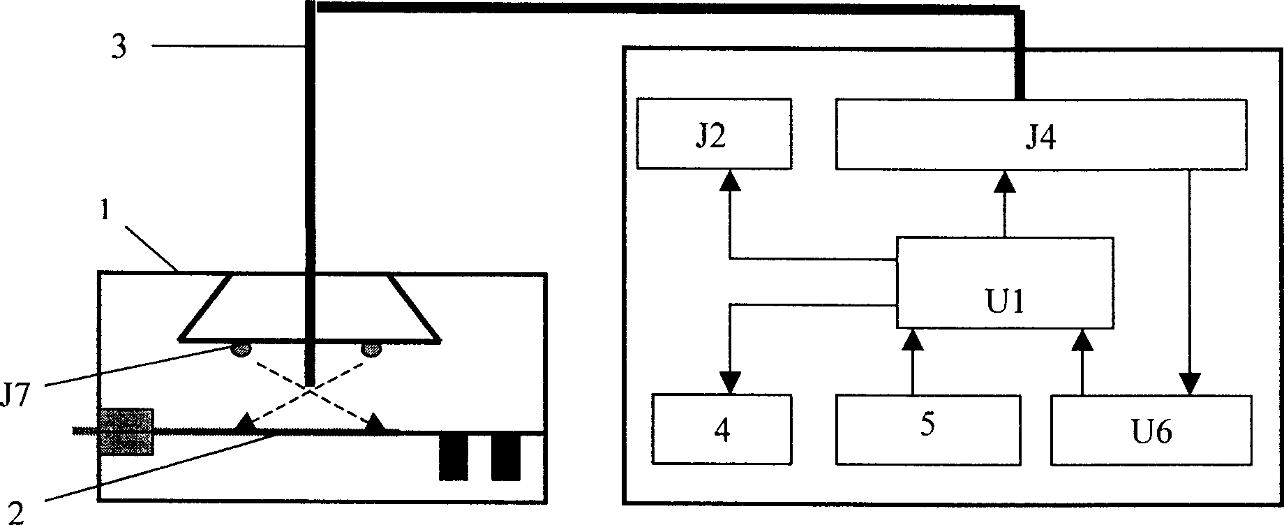
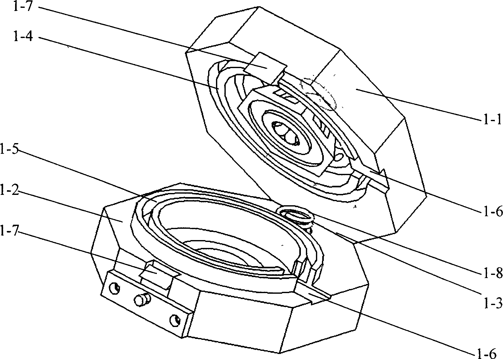
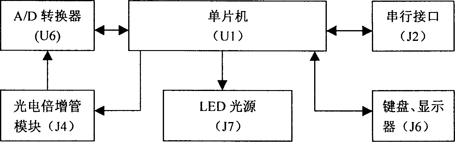
[0024] figure 1 shows the concrete structure of the present invention, by figure 1 It can be seen that the LED irradiation photosynthetic ability rapid detector includes darkroom 1, LED light source J7, optical fiber 3, photomultiplier tube module J4, A / D converter U6, single-chip microcomputer U1, input keyboard 5, display 4, serial interface J2, The LED light source J7 is located in the darkroom 1, one end of the optical fiber 3 extends into the darkroom 1, and the other end is connected with the photomultiplier tube module J4, and the photomultiplier tube module J4 is connected with the single-chip microcomputer U1 through the A / D converter U6, input keyboard 5, The display 4 is connected with the single-chip microcomputer U1 at the same time, and the single-chip microcomputer U1 is also connected with a serial interface J2, and can communicate with the computer through the serial interface J2. The structure of the darkroom 1 is as figure 2 shown by figure 2 It can be ...

Embodiment 2

[0027] This embodiment is the same as embodiment 1 except for the following features: the upper and lower chamber bodies of the darkroom are completely split and separated structures, and the internal structure is the same as that of embodiment 1; when not in use, the upper and lower chamber bodies can be Separate, and connect the upper and lower chambers when needed.

Embodiment 3

[0029] This embodiment is the same as Embodiment 1 except for the following features: the darkroom has an integrated structure, a living body insertion hole is provided on the side of the darkroom, and a light-shielding gasket is provided at a position close to the living body insertion hole in the darkroom, which can Compress the living body and block the light to make the dark room light-tight.


PUM


Abstract

This invention is a detector for capability of the LED irradiation photosynthesis. It contains the dark room, excitation mount for visible light, detection mount for dim light,A-D converter .The setup of thr darkroom is for intravital ertrance. The excitation mount for visible light is LED mount. The detection mount for dim light contains optical fibre,electron-multiplier phototube. The fibre connects the dark room and the electron-multiplier phototube. The date handling mount is singlechip systerm. It is connected to the electron-multiplier phototube by the A-D converter as well as through the control interface. This product is light and small, it is easy to remove and can be carried easily. So it can perform as a out-door somatometer. It conquers the existing product's weakness--big inaccuracy made by used as a somatometer. The structure is simple and appropriate. It is easy to operate and is very cheap. It is do good to its extention.

Description

technical field [0001] The invention relates to a device for measuring photosynthesis rate, in particular to a rapid detector for photosynthetic ability of light-emitting diode (LED) irradiation. Background technique [0002] The rate of photosynthesis is an important index to characterize the photosynthetic ability of plants. At present, in the measurement of photosynthetic rate, the widely used instrument is LI-62XX series photosynthetic rate measuring instrument. The principle is based on the CO of the blade in unit time and unit area 2 The amount of reduction to determine the photosynthetic rate of leaves. There are many problems in this instrument, which are mainly manifested in the following aspects: (1) The instrument is seriously restricted by external environmental factors during the measurement process. Such as light intensity, humidity, CO 2 Instantaneous changes in concentration will bring great differences to the measurement results. T...

Claims


Application Information

Patent Timeline
Patent Type & Authority Applications(China)
IPC IPC(8): G01N33/00
Inventor 邢达王俊生
Owner SOUTH CHINA NORMAL UNIVERSITY
Why Eureka
Try Eureka