Load bearing wall, and steel house using the load bearing wall

A technology for steel structures and load-bearing walls, applied to walls, building components, building structures, etc., can solve the problems of cost increase and other problems, and achieve the effect of sufficient vibration energy, excellent shear strength, and full absorption

Inactive Publication Date: 2005-11-09
NIPPON STEEL CORP +1
View PDF1 Cites 0 Cited by
  • Summary
  • Abstract
  • Description
  • Claims
  • Application Information

AI Technical Summary

Problems solved by technology

Therefore, in this case, there will be problems affecting the cost increase

Method used


Image

  • Load bearing wall, and steel house using the load bearing wall
  • Load bearing wall, and steel house using the load bearing wall
  • Load bearing wall, and steel house using the load bearing wall

Examples


Embodiment 1

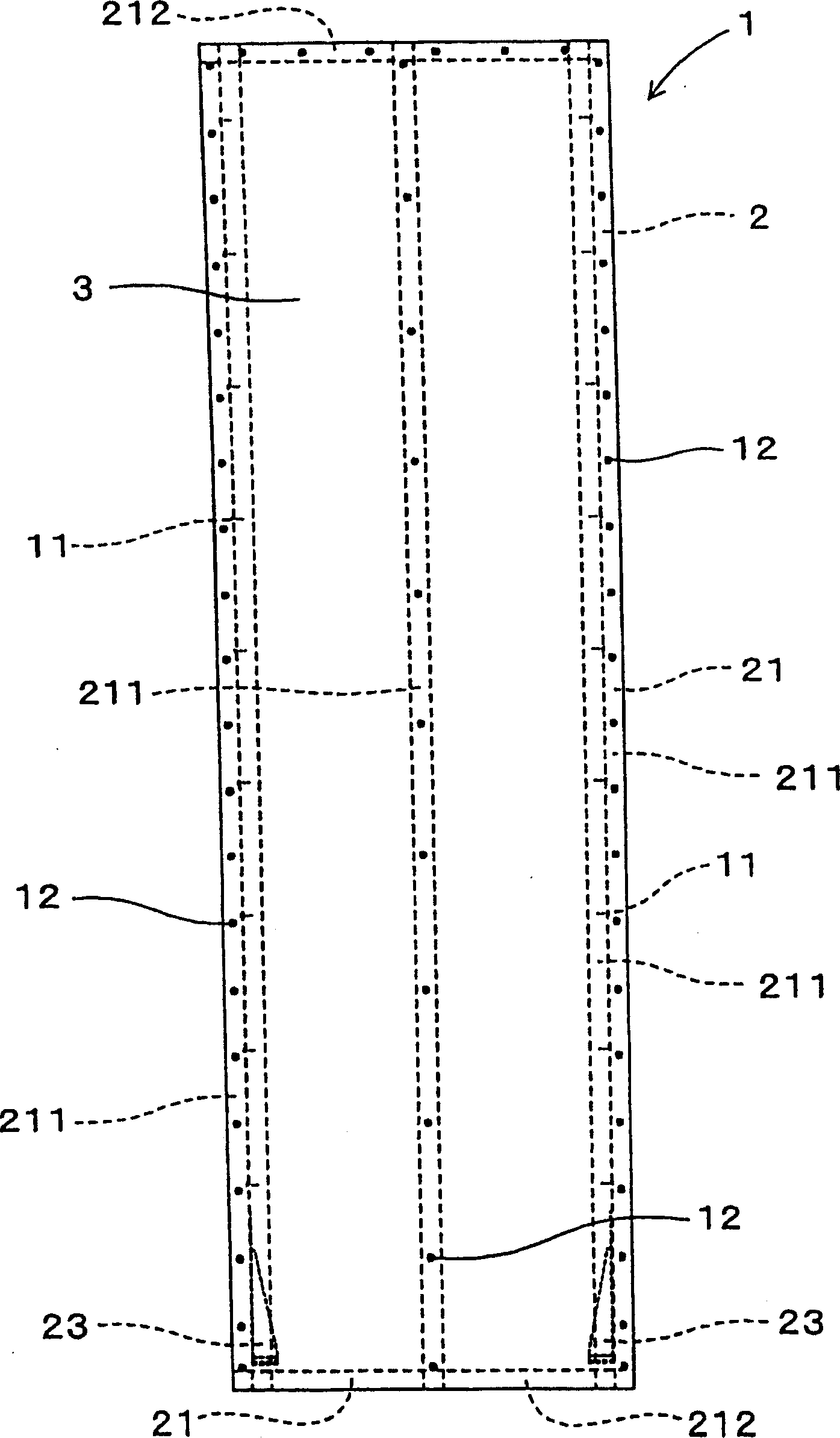
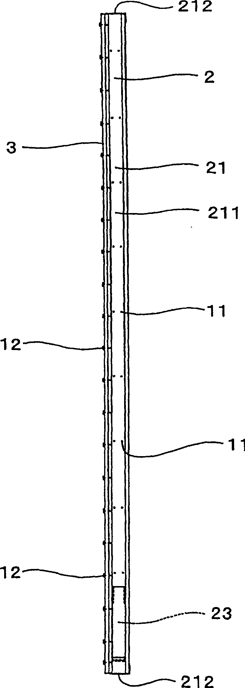
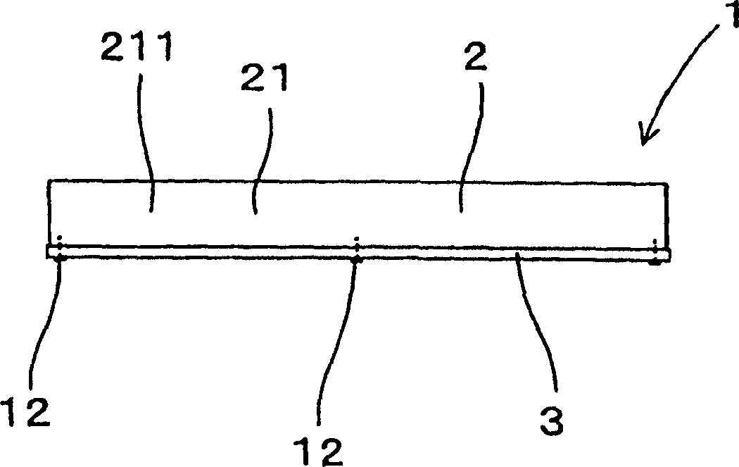
[0046] use Figure 1 to Figure 8 A load-bearing wall according to an embodiment of the present invention and a steel structure building using the same will be described.

[0047] The above bearing wall 1, such as Figure 1 ~ Figure 3 As shown, the steel frame body 2 ( Figure 4 ~ Figure 6 ), and the construction face material 3 fixed on the steel frame body 2.

[0048] The above-mentioned structural surface material 3 is composed of a cement board obtained as follows.

[0049] First, cement-like inorganic materials, silicic acid-containing substances, lightweight aggregates, and reinforcing fibers are dispersed in water to make slurry 41 . Such as Figure 7 As shown, the slurry 41 is machined and dehydrated to form a single-layer sheet. This single-layer sheet is wound on the production drum 51 , and laminated in multiple layers until reaching a predetermined thickness, whereby the laminated sheet 43 is formed. This laminated sheet 43 is cut out from the production drum ...

Embodiment 2

[0074] In this case, such as Figure 9 Shown is an example in which a so-called hacek-type papermaking machine 50 is used when manufacturing the structural surface material 3 .

[0075] This papermaking machine 50 has a manufacturing drum 51, a plurality of suction boxes 54 provided with a rotating cylinder (silinda) 53, and a felt that circulates between the manufacturing drum 51 and the rotating drum 53 while in contact with them. 55.

[0076] The slurry 41 thrown into the raw material box 52 of the papermaking machine 50 is supplied to each suction box 54 and dehydrated on the outer peripheral surface of the rotary cylinder 53 to form a thin raw material layer. This raw material layer is adsorbed onto the aforementioned felt 55 to form a single-layer sheet. In addition, layers of raw materials formed on the outer peripheral surfaces of the plurality of rotating cylinders 53 are superimposed on the felt 55 .

[0077] The single-layer sheet thus formed on the felt 55 is wo...

Embodiment 3

[0081] In this example, as shown in Figure 10, Figure 11 Shown is an example of evaluating the in-plane shear strength characteristics of the load-bearing wall of the present invention.

[0082] The load-bearing wall 1 used as the test object is the load-bearing wall ( Figure 1 ~ Figure 3 ). The outer dimensions of the load-bearing wall 1 are 3030 mm in length and 910 mm in width. The front and rear width of the steel frame body 2 is 92 mm, and the thickness of the structural surface material 2 is 12 mm.

[0083] The fixing positions of the above-mentioned small screws 12 are basically separated by 150mm for the vertical material 211 at the left and right ends of the above-mentioned steel structure frame body 2, and the horizontal material 212 at the upper and lower sides. Moreover, the vertical material 211 arrange|positioned at the center part of the left-right direction of the said steel structure frame body 2 is basically spaced apart by 300 mm. In addition, the diame...


PUM

PropertyMeasurementUnit
thicknessaaaaaaaaaa
thicknessaaaaaaaaaa
thicknessaaaaaaaaaa

Abstract

An inexpensive load bearing wall (1) capable of providing an excellent shearing strength and sufficiently absorbing vibration energy and a steel house using the load bearing wall, the load bearing wall (1) comprising a steel frame body (2) formed by framing shape steels (21) in rectangular shape and a structural surface material (3) fixed to the steel frame body (2), the structural surface material (3) further comprising a cement board provided by dispersing a cement based inorganic material, a silica containing-material, light-weight aggregate, and reinforcing fibers into water to form slurry, molding and dewatering the slurry to form a monolayer mat, winding the monolayer mat on a making roll by multiple layers until the thickness thereof becomes a specified thickness to form a laminated mat, cutting off the laminated mat from the making roll, and press-forming the laminated mat to manufacture a press mat, and curing the press mat.

Description

technical field [0001] The present invention relates to a load-bearing wall (supporting wall) composed of a steel structure frame formed by framing section steel into a rectangular shape, and a structural surface material fixed to the steel structure frame, and a steel structure room (スチ- luhouse). Background technique [0002] Conventionally, there has been a load-bearing wall composed of a steel structure frame formed by framing section steel in a rectangular shape, and a structural surface material fixed to the steel structure frame (see JP-A-2001-55807). [0003] That is, this load-bearing wall is formed by using light-gauge thin-plate steel for the frame body of the wall structure obtained by the usual frame structure wall construction method (2×4 construction method). In addition, as a structural surface material, a wood composite board with a thickness of about 9 mm is generally used. [0004] In addition, such a load-bearing wall constitutes a steel structure room....

Claims


Application Information

Patent Timeline
Patent Type & Authority Applications(China)
IPC IPC(8): E04B2/56B28B1/52C04B28/02E04B1/08E04B1/348E04C2/38
CPCB28B1/527B28B1/522C04B2111/2046E04B1/08C04B28/02C04B14/06C04B20/002C04B20/0048C04B40/006C04B40/0259E04B2/56
Inventor 村桥喜满藤内繁明田中浩史伊藤博
Owner NIPPON STEEL CORP
Why Eureka
Try Eureka