Super high vacuum system sample feeding apparatus

A new type of ultra-high vacuum technology, applied in measuring devices, instruments, scientific instruments, etc., can solve the problems of high production cost, complex structure, small room for modification, etc., and achieve good compatibility, simple and effective overall structure, and processing and manufacturing Use easy-to-use effects

Inactive Publication Date: 2005-11-23
INST OF PHYSICS - CHINESE ACAD OF SCI
View PDF0 Cites 12 Cited by
  • Summary
  • Abstract
  • Description
  • Claims
  • Application Information

AI Technical Summary

Problems solved by technology

At present, the structure of the sample transfer device in most ultra-high vacuum systems is relatively complicated, and there is l

Method used


Image

  • Super high vacuum system sample feeding apparatus
  • Super high vacuum system sample feeding apparatus
  • Super high vacuum system sample feeding apparatus

Examples


Embodiment 1

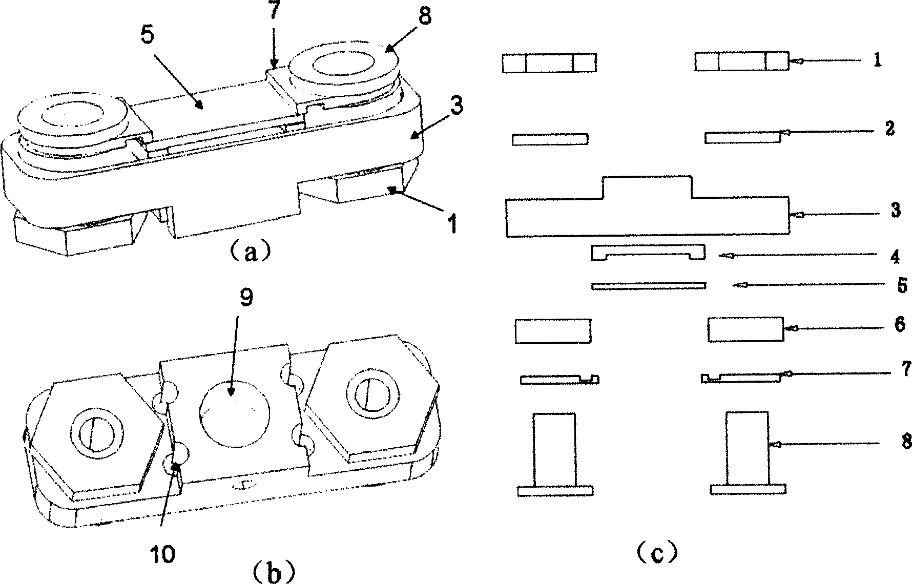
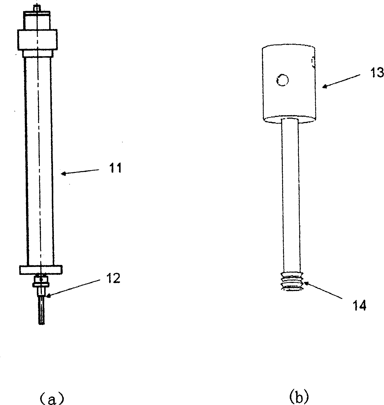
[0021] The present invention comprises: sample holder, sample transfer rod and sample receiving table, such as figure 1 As shown in a, b, and c, the sample support includes a rectangular parallelepiped molybdenum support 3, two hollow molybdenum screws 8 and an insulating lining 4. There are through holes at both ends of the molybdenum support 3 for installing the molybdenum screw 8 and the molybdenum support 3. There is a boss in the middle part of the lower part, and the boss has a threaded hole 9. The molybdenum screw 8 is fixed by the molybdenum nut 1 and the molybdenum bracket 3. The lower end of the nut of the molybdenum screw 8 is pierced with the first electrode 7, which is used to connect with the insulating lining. 4 together to fix the sample 5 and introduce current to the sample 5, between the first electrode 7 and the molybdenum support 3 and between the nut 1 and the molybdenum support 3 are respectively provided with insulating rings 2, 6, and the molybdenum supp...

Embodiment 2

[0023] Such as Figure 4 As shown in a, the difference between this embodiment and embodiment 1 is that a second electrode 20 and a heating resistor 19 are arranged in sequence between the sample 5 and the insulating lining 4, and a heating resistor 19 is arranged between the second electrode 20 and the molybdenum support 3. Another insulating ring 18 .

[0024] For high resistance (insulating) samples, direct heating with electric current is obviously not possible. In this embodiment, double-layer metal electrodes are used for high-resistance samples, the first electrode 7 is only used to fix the sample 5 , and the second electrode 20 is used to clamp the heating resistor 19 . When the current is passed through the two ends of the second electrode 20, the heating resistor 19 becomes hot, which indirectly heats the sample 5.

Embodiment 3

[0026] Such as Figure 4 As shown in b, the difference between this embodiment and embodiment 2 is that an insulating spacer 21 is provided between the sample 5 and the second electrode 20, and the first electrode 7 can be replaced by an insulator.

[0027] For the metal sample, considering that some occasions have special requirements for the grounding of the sample 5, one of the first electrodes 7 (two symmetrical ones) of the fixed sample 5 is replaced with an insulator, and the sample 5 and the second electrode 20 are connected simultaneously. Insulation, just can avoid electric current to pass through sample 5 and cause short circuit when heating.

[0028] In addition, it is also possible to use the Figure 5 The structures shown in a and b. Such as Figure 5 As shown in a, two unconnected metal pads 22 are padded on the insulating lining 4 of the sample holder, and the shapes of the two metal electrodes 7 used to clamp the sample 5 can also be changed accordingly, so ...


PUM


Abstract

The invention discloses a new pattern super high vacuum system sample transmission device which comprises: sample holder, sample transmission rod and sample receiving platform. Sample holder comprises rectangle molybdenum holder, two hollow molybdenum screws and concave insulating gasket, wherein both ends of molybdenum holder has through-hole used to fix molybdenum screws; in the middle of molybdenum holder's lower parts posits a boss which opens screw thread hole to match transmission rod and; molybdenum screw posits with molybdenum holder through nut; molybdenum screw and cap's lower has first electrode used to fix sample and flow current with insulating gasket; insulating circle are separately posited between first electrode and molybdenum holder and between cap and molybdenum holder. Different samples such as semiconductor, insulator and metal can use the invention to transmit and handle the sample in super high vacuum scanning tunneling microscope system, molecular beam epitaxy system, extremely condition electric transport testing system and its associating system.

Description

technical field [0001] The invention relates to a sample transmission device of an ultra-high vacuum system, which is especially suitable for scanning tunneling microscope (STM), molecular beam epitaxy (MBE) and extreme condition electric transport testing system. Background technique [0002] The ultra-high vacuum system refers to a system for growing, characterizing and measuring physical properties of different types of samples in an artificial ultra-high vacuum environment. At present, ultra-high vacuum systems have been used in various research fields such as semiconductors, physics, chemistry, materials and biological sciences. The sample transfer device is an important part of the ultra-high vacuum system. It usually consists of three parts: the sample holder, the sample transfer rod (or sample transfer hand) and the sample receiving table, which are used to transfer the sample to each part of the system. At present, the structure of the sample transfer device in mos...

Claims


Application Information

Patent Timeline
IPC IPC(8): G01N35/02
Inventor 王健蔡伟伟梁学锦刘慧陈东敏薛其坤
Owner INST OF PHYSICS - CHINESE ACAD OF SCI
Why Eureka
Try Eureka