
Low-ripple switch power amplifier for permanent magnet biased electromagnetic-bearing
A technology of electromagnetic bearing and switching power, applied in the direction of holding device, bearing, shaft and bearing with magnetic attraction or thrust, which can solve the problem of increasing switching loss, large iron loss and copper loss of electromagnetic bearing, large output current ripple, etc. problem, to achieve the effect of reducing output current ripple, flexible waveform generation, and simple circuit design
- Summary
- Abstract
- Description
- Claims
- Application Information
AI Technical Summary
Problems solved by technology
Method used
Image

Examples
Embodiment Construction
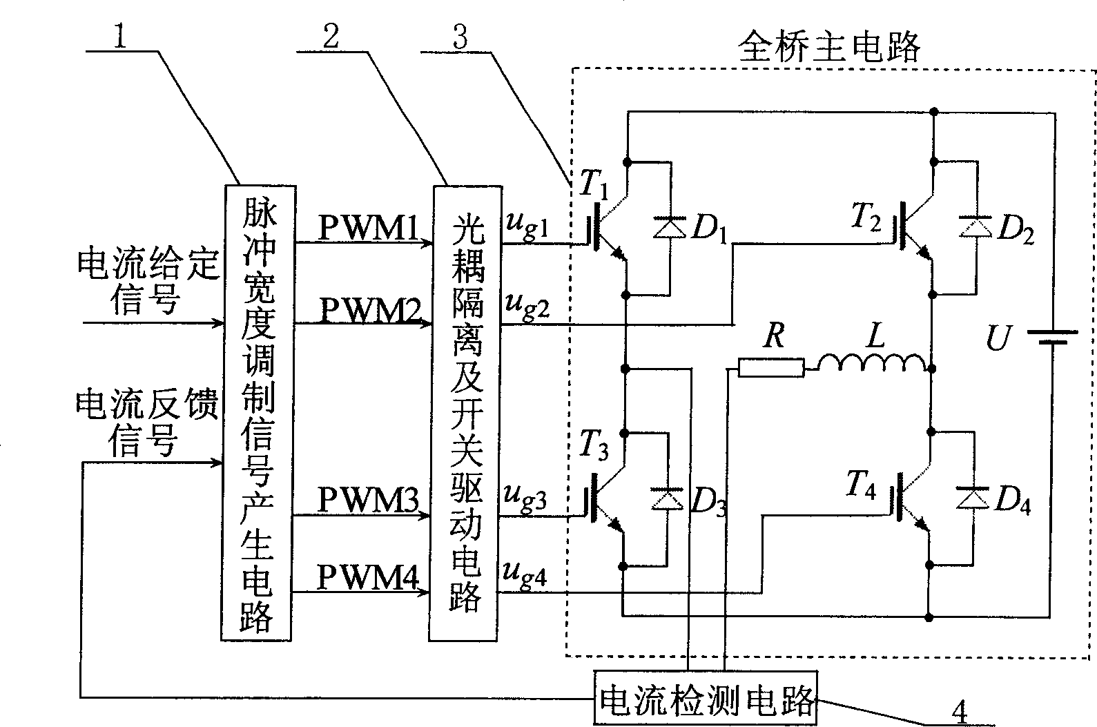
[0012] The block diagram of the circuit structure of the present invention is as figure 1 As shown, it can be divided into four parts, namely pulse width modulation signal generation circuit, optocoupler isolation and switch drive circuit, full bridge main circuit and current detection circuit. The pulse width modulation signal generating circuit is a key component of the present invention, and the present invention is realized by using analog circuits and digital circuits made up of discrete components, and can also be digitally realized by software programming. The optocoupler isolation circuit uses chip 6N137, and the switch drive circuit uses chip IR2110. The current detection circuit adopts the current sensor LA28-NP of LEM Company.
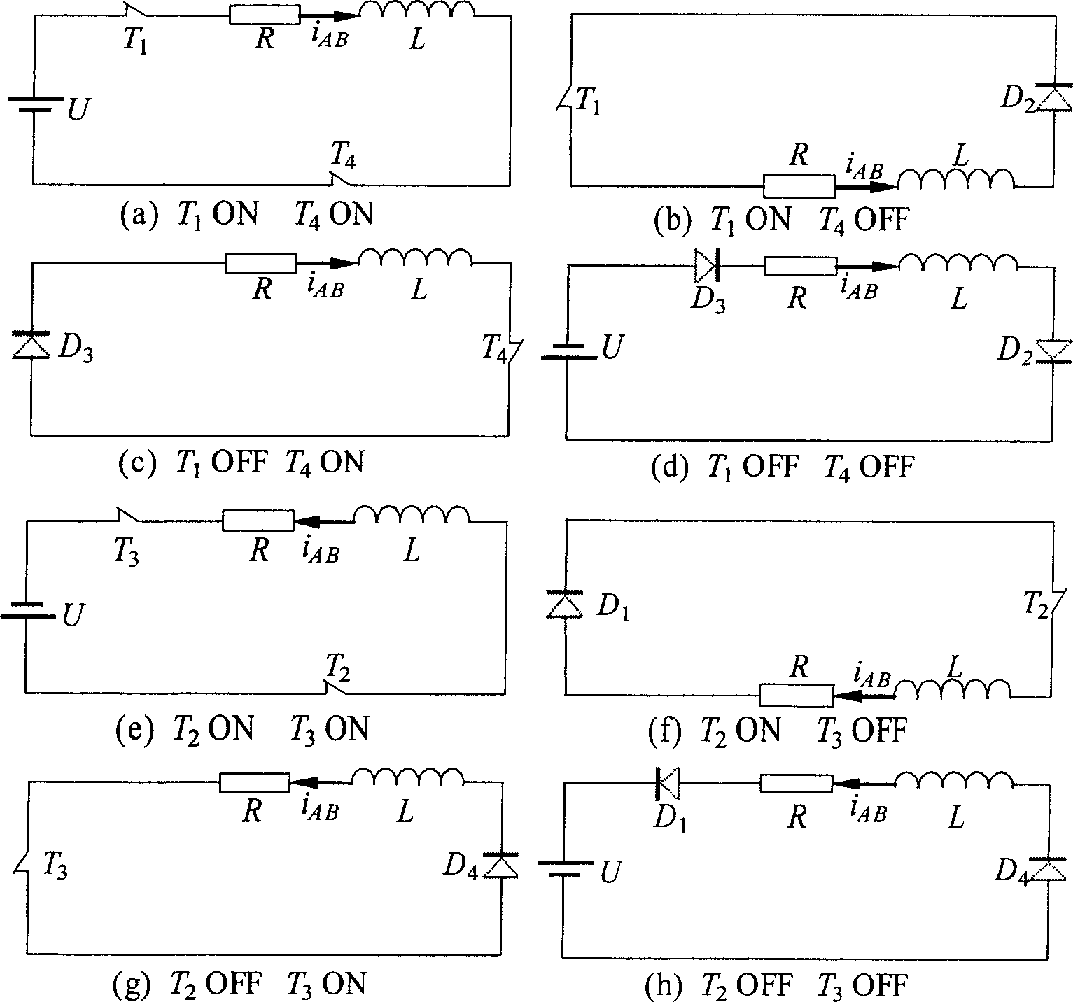
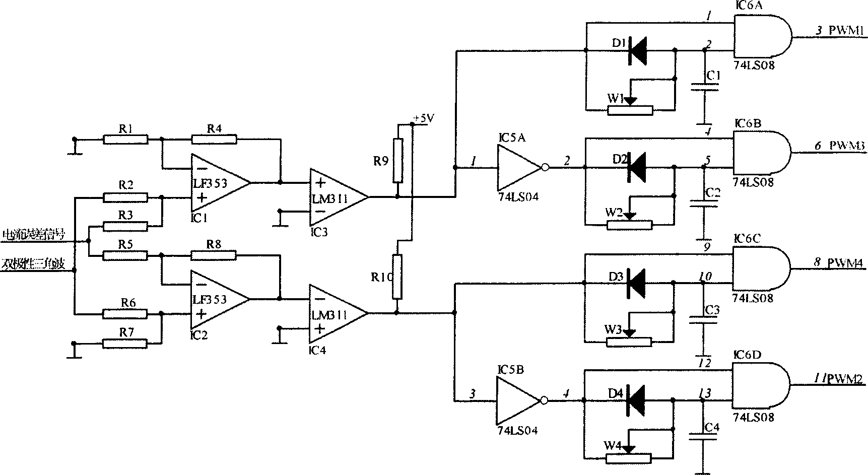
[0013] The following is attached figure 2 , the principle of the PWM modulation circuit adopted in the present invention will be described.
[0014] For the electromagnetic bearing switching power amplifier, through the four power switch...
PUM
 Abstract
Description
Claims
Application Information