Micro flow control chip negative pressure sampling and separating device

A microfluidic chip, negative pressure technology, applied in measurement devices, microbial determination/inspection, material analysis by electromagnetic means, etc., can solve the problems of high voltage infusion equipment, affecting safe operation, etc., and achieve a simple structure. , The effect of simple operation and convenient operation

Inactive Publication Date: 2006-01-04
ZHEJIANG UNIV
View PDF0 Cites 14 Cited by
  • Summary
  • Abstract
  • Description
  • Claims
  • Application Information

AI Technical Summary

Problems solved by technology

If the conductive sample or electrophoresis buffer leaks out of the infusion device, it will cause the infusion device to be charged with high voltage and affect the safe operation

Method used


Image

  • Micro flow control chip negative pressure sampling and separating device
  • Micro flow control chip negative pressure sampling and separating device

Examples


Embodiment 1

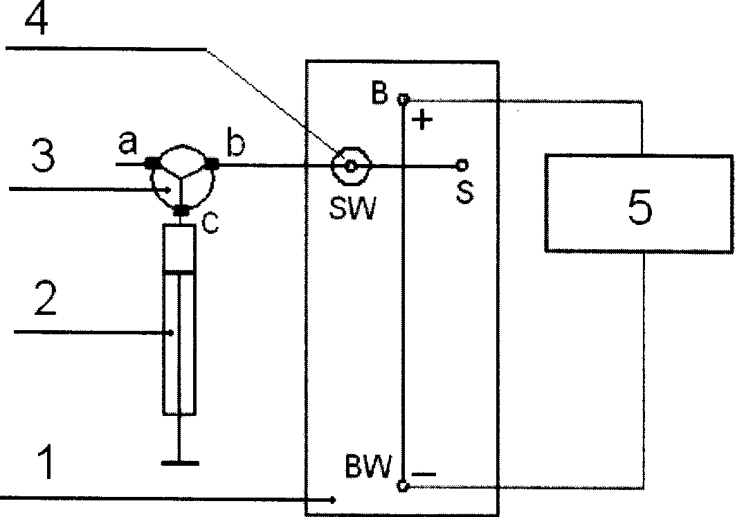
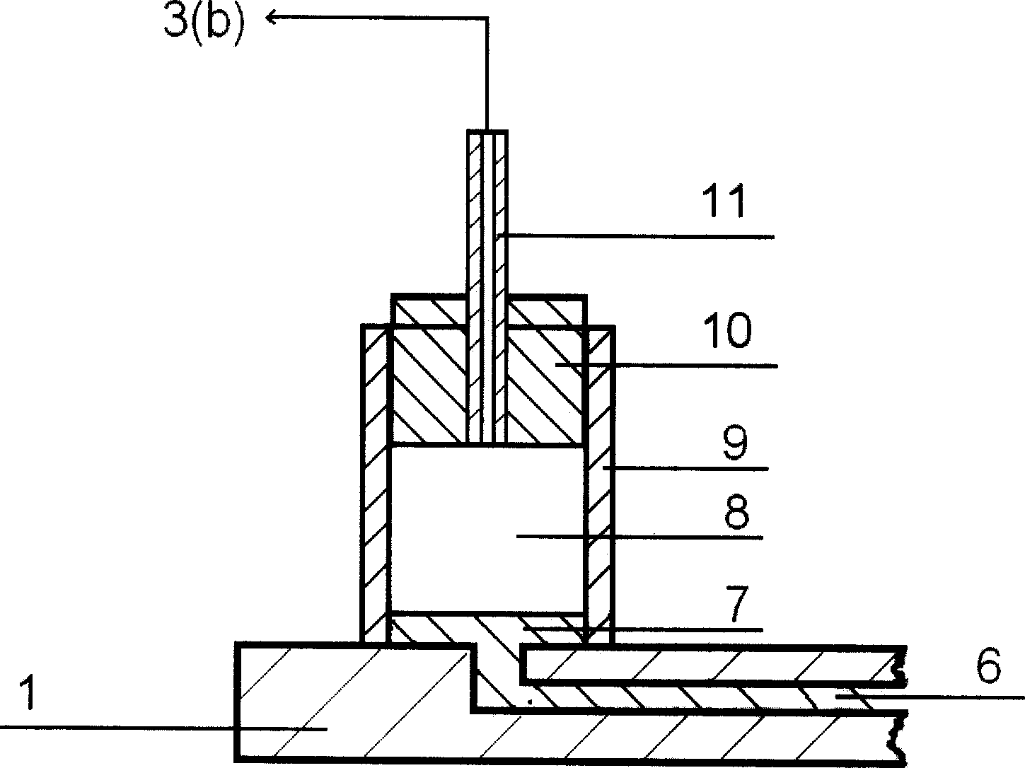
[0013] See figure 1 , figure 2 , The channel between B and BW on the microfluidic chip 1 is the separation channel, the channel between S and SW is the injection channel, and B, BW, S and SW represent the buffer reservoir and the buffer waste reservoir respectively. Liquid pool, sample storage pool and sample waste pool. The a port of the three-way valve 3 is directly connected to the atmosphere, the plunger pump 2 is connected to the c port of the three-way valve 3, and the b port of the three-way valve 3 is connected to the port 4 through the connecting pipe 11. The port 4 is installed in the microfluidic control Above the chip sample waste pool SW. Add the sample solution to the sample reservoir S on the microfluidic chip, and add different volumes of electrophoresis buffer to the other reservoirs B, SW, and BW to maintain the liquid level of the reservoirs B and BW at both ends of the separation channel Similarly, the height of the liquid level in the sample reservoir S is le...


PUM


Abstract

The negative pressure sampling and separating device with micro flow control chip consists of micro flow control chip, plunger pump, three-way valve, interface and high voltage power supply. It features the three-way valve with the first end communicated with atmosphere, plunger pump connected to the third end of the three-way valve, the second end of the three-way valve connected to the interface via connecting pipeline, the micro flow control chip with buffering liquid storing pond B, waste buffering liquid storing pond BW, sample storing pond S and waste sample storing pond SW, the interface on the waste sample storing pond SW, micro flow control chip sampling channel S-SW, separating channel B-BW, and the high voltage power source connected across the channel B-BW. The present invention has simple structure, fast sampling and operation safety.

Description

Technical field [0001] The invention relates to a microfluidic chip capillary electrophoresis analysis technology, in particular to a sample injection and separation device on a microfluidic chip capillary electrophoresis. Background technique [0002] Since the concept of micro-total analysis system was put forward in 1990, microfluidic chip technology has opened up a broad space for development in the fields of medicine and life sciences. Microfluidic chip capillary electrophoresis technology has been used in DNA sequencing, separation and identification of DNA fragments, separation and determination of amino acids, peptides, and proteins, and the analysis of components in single cells. [0003] For the above-mentioned applications, accurate control of the sample injection volume of the skin upgrade is the key to separation and determination. At present, electric sampling based on electroosmotic flow is commonly used for sampling, such as electric clamp injection, suspension sa...

Claims


Application Information

Patent Timeline
IPC IPC(8): G01N27/453G01N1/00G01N35/10C12Q1/00
Inventor 殷学锋张磊
Owner ZHEJIANG UNIV
Why Eureka
Try Eureka