Gear spin pressure forming method and its device

A spinning forming and gear technology, applied in the field of gear spinning forming method and its device, can solve the problems of equipment control difficulty and manufacturing cost increase, synchronization and accuracy problems, increase of hydraulic control system, etc., to eliminate discontinuity , high processing cost, improve the effect of mechanical equipment

Inactive Publication Date: 2006-01-11
SOUTH CHINA UNIV OF TECH
View PDF0 Cites 11 Cited by
  • Summary
  • Abstract
  • Description
  • Claims
  • Application Information

AI Technical Summary

Problems solved by technology

However, the radial feed movement of the rotary wheel is generally driven by hydraulic pressure, so the synchronization and accuracy of the rotary wheel feed often become a technical problem, and the hydraulic control system will be added to the entire machine tool, resulting in difficulty in equipment control and increase in manufacturing costs

Method used


Image

  • Gear spin pressure forming method and its device
  • Gear spin pressure forming method and its device
  • Gear spin pressure forming method and its device

Examples


Embodiment

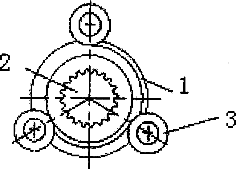
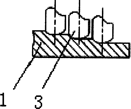
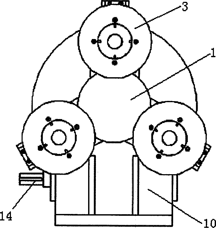
[0031] like figure 1 , 2 As shown, the gear spinning forming method of the present invention is: the cup-shaped blank 1 is set on the external tooth-shaped mandrel 2 that rotates with the main shaft, and the three rotary wheels 3 are uniformly spaced at 120° along the circumferential direction of the blank's outer peripheral surface. set, and there are axial offset and radial offset between each other, the servo motor drives three rotary wheels 3 through the worm 14, the worm wheel 15 and the Archimedes spiral disk 6 to carry out radial feed movement, and the rotation of the rotary wheels 3 It moves and presses on the blank 1, so that the blank 1 undergoes plastic deformation to become an internal gear.

[0032] The cup-shaped blank 1 is processed by sheet metal stamping and drawing or deep-drawing spinning. Since the volume distribution of deformed metal during gear spinning is relatively large, thick-walled blanks must be used for gear spinning.

[0033] By adopting the ge...


PUM


Abstract

A spinning method for shaping a gear includes such steps as installing a cup-shaped gear blank onto a gear mould rotating with mainshaft, uniformly installing three spinning wheels at intervals of 120 deg to surround said gear blank, and driving said three spinning wheels by motor via worm-gear unit and Archimedes' spiral disc to squeeze said blank to form a gear. Its apparatus is composed of machine frame, Archimedes' spiral disc and three spinning wheels.

Description

technical field [0001] The invention relates to the field of plastic processing methods and equipment in mechanical engineering, in particular to a gear spinning forming method and a device thereof. Background technique [0002] For a long time, gear processing has been completed on special equipment such as gear shaping machines and gear hobbing machines. After the forging billet is cut, the fiber structure is cut off. are relatively low. In addition, for some complex internal gears, such as cup-shaped (bottomed) thin-walled internal gears in clutches, reducers, and transmissions, due to the thin wall and bottom, when using traditional cutting methods, the bottom needs to be left The sipe makes this part a stress concentration area, and its strength is greatly weakened. Therefore, it is necessary to use stamping technology to form the bottom cup shape and use cutting technology to process the inner teeth, and then use welding methods to make it, whi...

Claims


Application Information

Patent Timeline
Patent Type & Authority Applications(China)
IPC IPC(8): B21D22/14
Inventor 夏琴香
Owner SOUTH CHINA UNIV OF TECH
Why Eureka
Try Eureka