Method of manufacturing segment for flat commutator

A technology of a commutator piece and a manufacturing method, which is applied in the manufacture of commutators, the manufacture of stator/rotor bodies, electromechanical devices, etc., can solve the problems of unfavorable manufacturing costs, poor material utilization, and low surface hardness, and achieve cheap processing. Effect

Active Publication Date: 2006-01-18
MITSUBA CORP
View PDF0 Cites 1 Cited by
  • Summary
  • Abstract
  • Description
  • Claims
  • Application Information

AI Technical Summary

Problems solved by technology

Therefore, although the workload after molding is reduced, the manufacturing workload of the commutator sheet is increased, and effective cost reduction cannot be achieved.
In addition, since the trimmed portion of the commutator profile 57 is relatively large when forming the commutator piece...

Method used


Image

  • Method of manufacturing segment for flat commutator
  • Method of manufacturing segment for flat commutator
  • Method of manufacturing segment for flat commutator

Examples


Embodiment 1

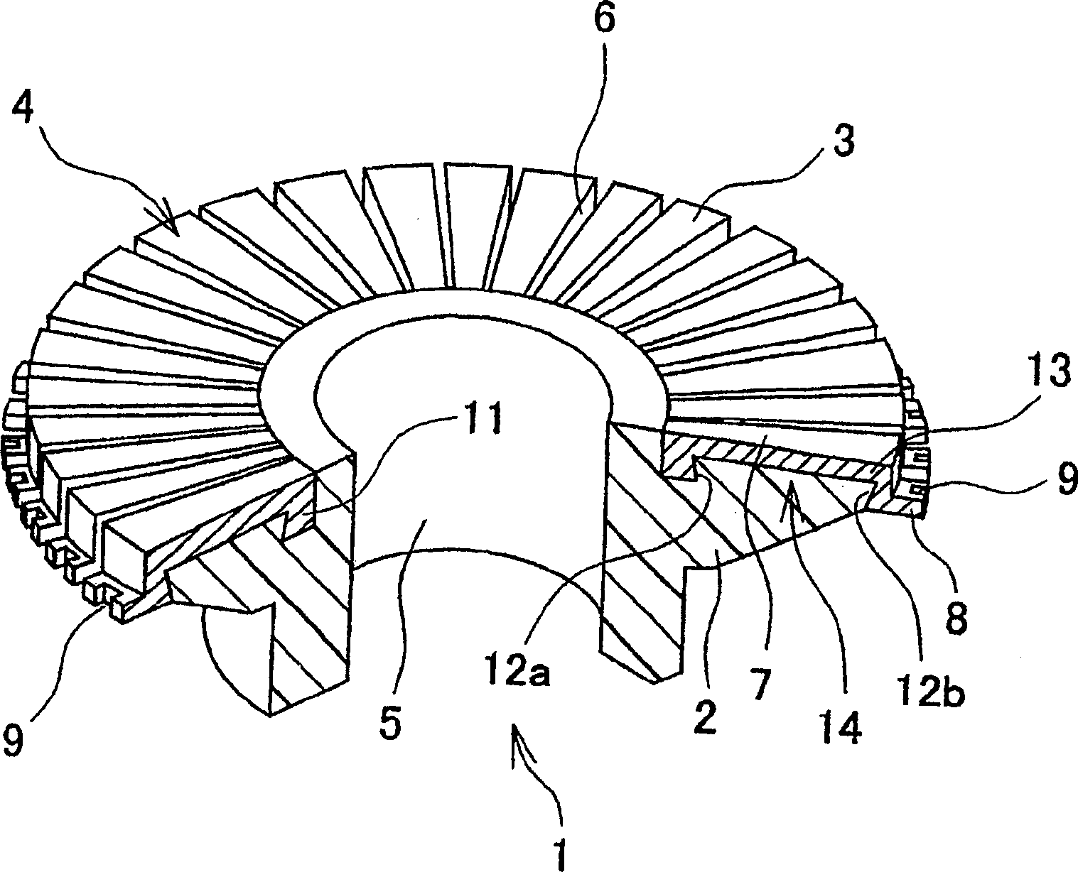
[0026] Embodiments of the present invention will be described in detail below based on the drawings. figure 1 It is a partially cutaway perspective view showing an example of a flat commutator using commutator segments manufactured by the manufacturing method of the present invention.

[0027] Such as figure 1 As shown, the commutator 1 constitutes a flat structure and is used in starter motors, fuel supply pumps in fuel tanks, and the like. The commutator 1 has a support part 2 made of synthetic resin and a plurality of metal commutator segments 3; the commutator segments 3 and the support part 2 are integrally molded. The surface of the commutator sheet 3 ( figure 1 The upper surface) becomes the brush sliding surface 4, which is in contact with the brush not shown in the figure from the axial direction.

[0028] In such a commutator 1, each commutator segment 3 is mounted on a circular frame, and the whole is molded with synthetic resin in this state. A rotating shaf...

Embodiment approach 2

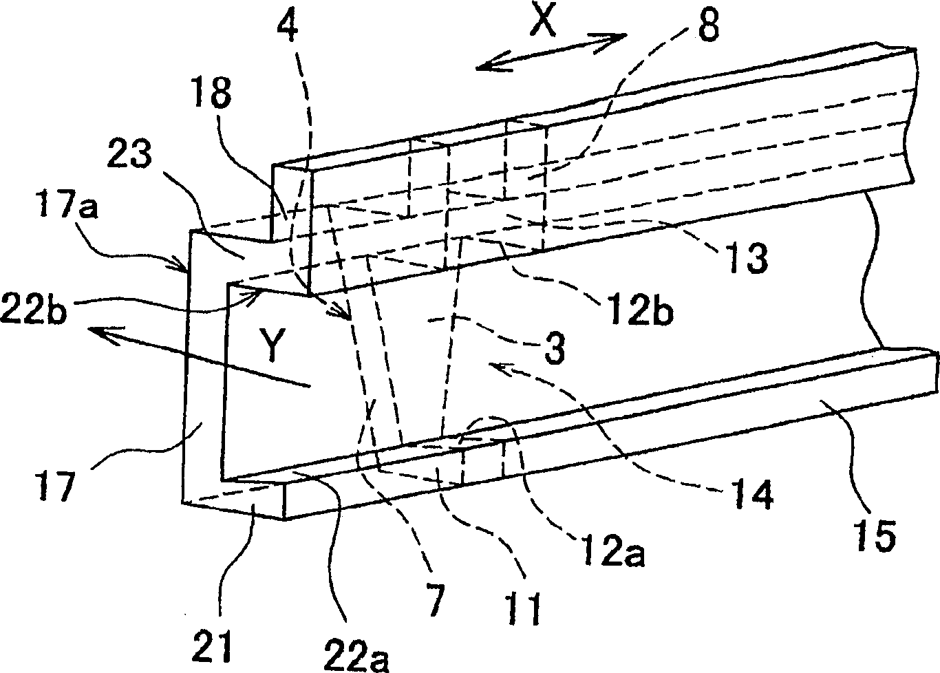
[0039] Figure 5 It is an explanatory diagram showing a method of manufacturing a commutator segment according to Embodiment 2 of the present invention. In addition, the same parts and components as those in Embodiment 1 are given the same reference numerals, and description thereof will be omitted.

[0040] In the manufacturing method of Embodiment 2, in order to further improve the material utilization rate of the commutator sheet 3, as Figure 5 As shown, the commutator profile (base metal) 25 is subjected to so-called cross-cutting. The commutator profile 25 punches adjacent commutator segments 3 in vertically opposite directions to form a portion having the same cross-sectional shape as that of the commutator segments 3 , forming a vertically symmetrical shape. That is, the outer peripheral forming portion 18 of the commutator profile 15 having the same cross-sectional shape as that of the commutator segment 3 is provided at both ends of the commutator profile 25 to for...


PUM


Abstract

A method of manufacturing a segment (3) for a flat commutator, comprising the steps of forming a theta section bar (15) having the same cross sectional shape as that of the segment (3) by drawing, punching out the theta section bar (15) in a direction Z perpendicular to a drawing direction X to form the segment (3) for the flat commutator, wherein the drawing direction X for the theta section bar (15) is aligned in the generally same direction as the slidable contact direction of a brush on the segment (3) and a draw-finished surface is formed to be used as a brush sliding surface (4) of the segment (3), and an anchor part (14) forming an extraction stopper for the segment (3) is formed on the theta section bar (15) in drawing, whereby the segment for the flat commutator capable of preventing the leakage of resin in a resin mold process can be easily manufactured at a low cost.

Description

technical field [0001] The present invention relates to a method for manufacturing a commutator for a rotating electrical machine, and in particular to a method for manufacturing commutator segments in a disk-type flat commutator. Background technique [0002] In recent years, among motors used in electric power steering devices, engine starters, fuel pumps, etc., motors using flat type commutators (planar commutators) have appeared due to demands for device miniaturization. Unlike common cylindrical commutators, this flat commutator has a disk-shaped brush sliding surface extending radially from the axis of rotation, and is integrally molded with a metal part called commutator metal and synthetic resin. After integral molding, the commutator metal is cut radially and separated in the circumferential direction to form a plurality of commutator segments in a mutually insulated state. In addition, the brush is in sliding contact with the brush sliding surface made of the comm...

Claims


Application Information

Patent Timeline
IPC IPC(8): H02K13/00H02K15/02H01R39/06H01R43/06
CPCH01R39/06H01R43/06
Inventor 上原修二南秀行岩下和男堀内秀基矶田稔竹部康弘小岛理规石关隆行肉户充
Owner MITSUBA CORP
Why Eureka
Try Eureka