Electrode and metallic vapour discharge lamp

A conductive metal and electrode technology, applied in the field of electrodes, can solve problems such as uneven distribution of heat along the circumferential direction, unguaranteed strength, and difficulty in reliable interface bonding, and achieve the effects of reducing discreteness and improving welding strength

Inactive Publication Date: 2006-03-01
PANASONIC CORP
View PDF0 Cites 2 Cited by
  • Summary
  • Abstract
  • Description
  • Claims
  • Application Information

AI Technical Summary

Problems solved by technology

However, in such a laser welding method, since the cross-sectional shape of the laser beam is approximately circular, when the laser beam is irradiated on the butted part, the heat is unevenly distributed in the circumferential direction, and it is difficult to securely ...

Method used


Image

  • Electrode and metallic vapour discharge lamp
  • Electrode and metallic vapour discharge lamp
  • Electrode and metallic vapour discharge lamp

Examples


Embodiment 1

[0047] Next, specific examples corresponding to Embodiment 1 will be described.

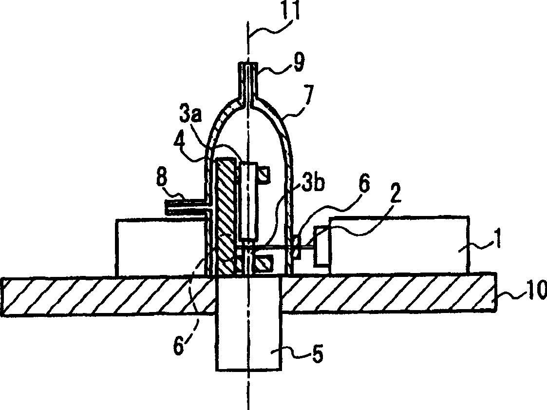
[0048] The first electrode part 3a is a rod-shaped part with a diameter of 1.2 mm and a length of 8.25 mm, which is composed of a conductive cermet with a composition composition of 50% alumina and 50% molybdenum (by weight). For the second electrode part 3b, a rod-shaped part made of tungsten and having a diameter of 0.71 mm and a length of 22.3 mm was used.

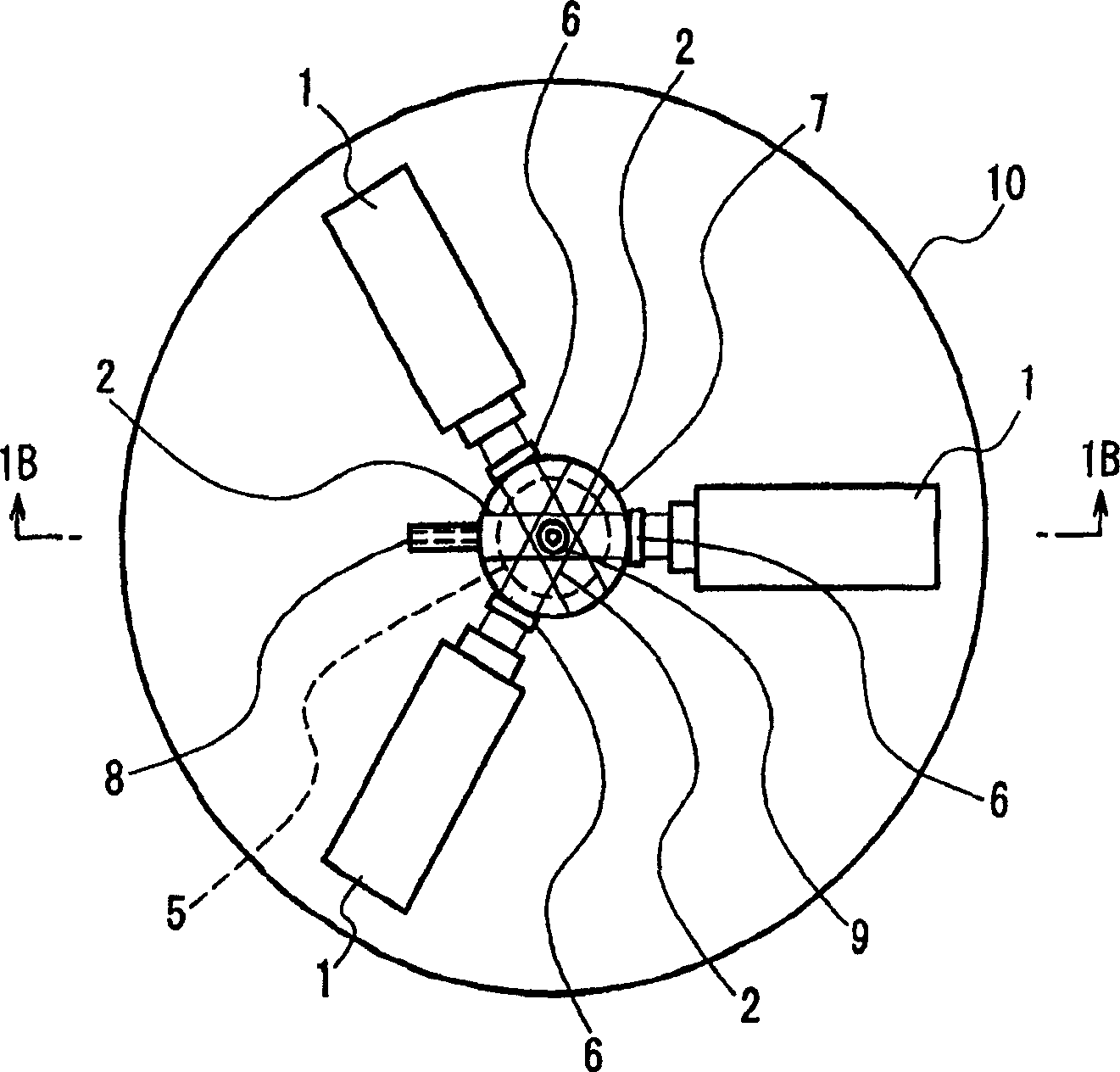
[0049] The laser irradiation unit 1 uses a semiconductor laser (wavelength 800 nm, output power 130 W), and three units are radially arranged at intervals of 120 degrees on the horizontal plane around the center line 11 . Each laser 2 having a rectangular (WL3mm×WS0.5mm) cross-sectional shape is irradiated on the second electrode part at a distance D=0.5mm downward from the butt surface 17 of both the first electrode part 3a and the second electrode part 3b 3b on. The laser irradiation time was 1.3 seconds.

[0050] A schematic cross-se...

Embodiment 2

[0064] Next, specific examples corresponding to Embodiment 2 will be described.

[0065] Using the same first electrode part 3a made of conductive cermet and the second electrode part 3b made of tungsten as in Example 1 shown in Embodiment 1, the two electrode parts are welded according to the welding method of Embodiment 2. .

[0066] The welded portion of the obtained electrode, and the welded portion 18 of Example 1 are schematically shown. Figure 4 Similarly, a Mo-W alloy layer is formed on the entire end surface of the second electrode component 3b, and an aluminum oxide layer is formed on the outer periphery of the welded portion. The outer diameter of the welded portion satisfies the dimensional accuracy of the electrode (1.2mm±0.2mm). In addition, the mechanical strength of the welded portion and its discreteness were at the same level as those of the electrode of Example 1.

[0067] In the above-mentioned Embodiments 1 and 2, the coils 60a, 60b are provided only o...


PUM

PropertyMeasurementUnit
Diameteraaaaaaaaaa
Diameteraaaaaaaaaa

Abstract

An electrode of the present invention includes a first electrode part that is in a rod shape and a second electrode part that is in a rod shape and has a smaller diameter than that of the first electrode part, with the first and second electrode parts being welded and integrated with each other in a state in which ends thereof are brought into contact. In the electrode, the first electrode part is made of a conductive cermet, the second electrode part is made of tungsten, and in a welded portion where the first and second electrode parts are welded, an alloy layer comprising molybdenum composing the conductive cermet of the first electrode part and tungsten of the second electrode part covers the whole surface of an end of the second electrode part. Furthermore, the present invention also relates to a metal vapor discharge lamp, which has aluminous tube including a main tube with a discharge space, tubules connected at both ends of the main tube, and electrodes respectively inserted into the tubules.

Description

technical field [0001] The present invention relates to an electrode which can be advantageously used in a luminous tube of a metal vapor discharge lamp. Furthermore, the invention relates to metal vapor discharge lamps. Background technique [0002] In recent years, a metal vapor discharge lamp using a ceramic luminous tube with good heat resistance has been developed to achieve high color rendering and energy saving, but the manufacturing process has become more complicated. [0003] Next, a conventional manufacturing method of an electrode used in a discharge lamp will be described. [0004] Figure 9 It is a side sectional view schematically showing a conventional electrode manufacturing method for welding two rod-shaped electrode parts. Figure 9 Among them, 3a, 3b are two rod-shaped electrode parts to be welded, and 20a, 20b are a pair of electrodes of the resistance welding machine. The electrode parts 3a, 3b are respectively held by a pair of electrodes 20a, 20b, a...

Claims


Application Information

Patent Timeline
IPC IPC(8): H01J61/06
Inventor 川村龙也小林寿蔵榎并博司西浦义晴梁田隆春
Owner PANASONIC CORP
Why Eureka
Try Eureka