Automatic chip feeder and control thereof

A fully automatic, control box technology, applied in semiconductor/solid-state device manufacturing, electrical components, circuits, etc., can solve problems such as mechanical multi-task scheduling, and achieve the effects of overcoming interface design difficulties, convenient management and construction, and rapid packaging

Inactive Publication Date: 2006-03-15
SOUTH CHINA UNIV OF TECH
View PDF0 Cites 13 Cited by
  • Summary
  • Abstract
  • Description
  • Claims
  • Application Information

AI Technical Summary

Problems solved by technology

The core loading machine realizes the quality inspection and fast binding of the chip, and quickly packs the triode, and at the same time solves the technical problem of complex mechanical multi-task scheduling of this type of equipment

Method used


Image

  • Automatic chip feeder and control thereof
  • Automatic chip feeder and control thereof
  • Automatic chip feeder and control thereof

Examples


Embodiment Construction

[0037] The present invention will be described in further detail below in conjunction with the accompanying drawings and embodiments, but the implementation of the present invention is not limited thereto.

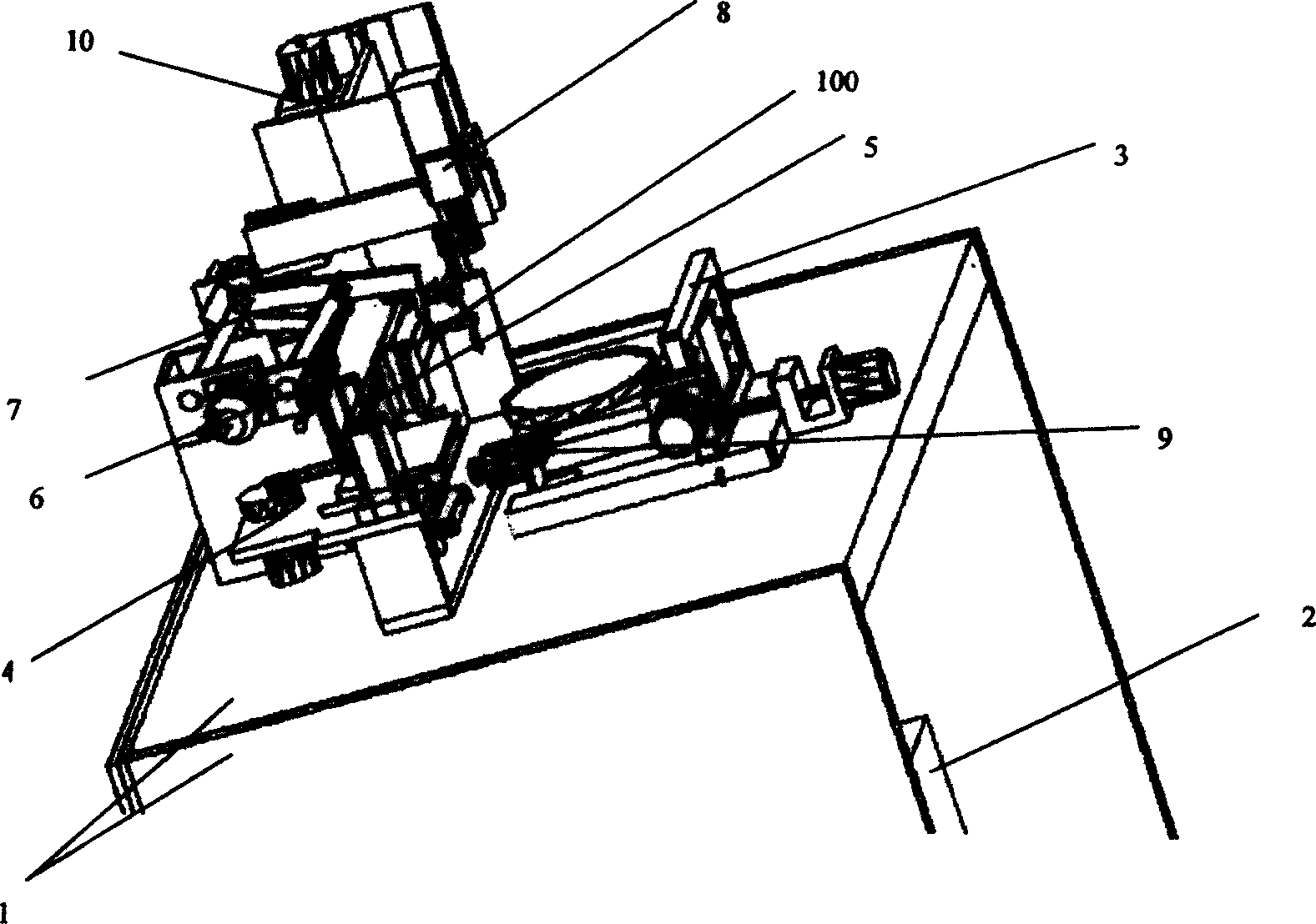
[0038] Such as figure 1As shown, the fully automatic core loading machine described in this embodiment includes a frame 1, a control box 2 is fixed at the lower end of the frame 1, a wafer table 3 and a feeding chute 5 are installed on the top, and the wafer table 3 is connected with a thimble 9, and the feeding chute 5 The two ends are respectively connected with a feeder 4 and a feeder 10, and are connected with a claw 6 and a welding arm 7, an image acquisition device 8 is installed above it, a heater 100 is installed below it, and the image acquisition device 8 is connected with the control box. connected to the control circuit. Among them, the frame 1 provides a stable operation platform for the whole machine, and at the same time protects the control box 2; the cont...


PUM


Abstract

The die bonder includes a machine frame. A control box is located at lower end of machine frame, and wafer bed and chute feeder are located on top of it. Under the wafer bed, the thimble is mounted. At the both ends of chute feeder, the loader and lay off machine are separately connected, and the claw and welding arm are also connected. The image collection device is located above it, and a heater is located under it. The image collection device is connected with the control circuit in the control box.

Description

technical field [0001] The invention relates to the technical field of chip production equipment in optical-mechanical-electrical integration, in particular to a fully automatic core loading machine and a control method thereof. Background technique [0002] The core and key equipment in IC manufacturing includes two parts: core making (pre-process) and packaging (post-process). The development trend of pre-process equipment is to develop new ultra-fine lithography machines and other equipment; while post-process equipment is to develop high-speed, high-precision, low-cost packaging equipment that is compatible with denser, smaller and lighter new packaging processes, and Realize the complete automation of the entire encapsulation process. [0003] The core loading machine is one of the key equipments in the semiconductor post-process production line. It mainly completes various reliable quality inspections and precise positioning of the chips, and se...

Claims


Application Information

Patent Timeline
Patent Type & Authority Applications(China)
IPC IPC(8): H01L21/50H01L21/68H01L21/66
Inventor 胡跃明戚其丰廖广军
Owner SOUTH CHINA UNIV OF TECH
Why Eureka
Try Eureka