Vibrating motor and portable terminal apparatus using same

A technology of vibrating motors and stator yokes, applied in the direction of using vibrating fluids, manufacturing motor generators, electromechanical devices, etc., can solve the problems of difficult rotating torque, difficult assembly, restrictions, etc., achieve effective driving torque, and achieve uniformity , the effect of imbalance suppression

Inactive Publication Date: 2006-03-15
MINEBEA MOTOR MFG
View PDF1 Cites 3 Cited by
  • Summary
  • Abstract
  • Description
  • Claims
  • Application Information

AI Technical Summary

Problems solved by technology

Therefore, the use is determined, and it is difficult to apply to an arbitrary use
[0016] (2) Since the bipolar stator is arranged opposite to the rotor made of bipolar permanent magnets, it becomes difficult to uniformly generate torque for rotation around the rotor
In addition, due to the small number of magnetic poles, the rotation angle of each magnetic stage becomes large, and it becomes difficult to adjust the starting characteristics and braking characteristics
[0017] (3) Since the number of magnetic poles is two, the rotation angle of each magnetic pole becomes larger, making it difficult to adjust the fine rotation angle
[0018] (4) The method of determining the direction of rotation becomes complicated, and the control of the start time and current value is difficult
Therefore, in general, the vibration motor is long in the direction of the rotor axis, and the target equipment to which it can be connected is limited due to the accommodation space
For example, when considering application to a cellular phone, in order to feel the vibration even if it is put in a pocket or the like, a fairly strong vibration energy is required, and in order to satisfy this, the vibration motor becomes long and large in the direction of the rotor axis , and assembly becomes difficult

Method used


Image

  • Vibrating motor and portable terminal apparatus using same
  • Vibrating motor and portable terminal apparatus using same
  • Vibrating motor and portable terminal apparatus using same

Examples


no. 1 example

[0060] (structure)

[0061] A typical embodiment of the vibration motor of the present invention includes a stepping motor.

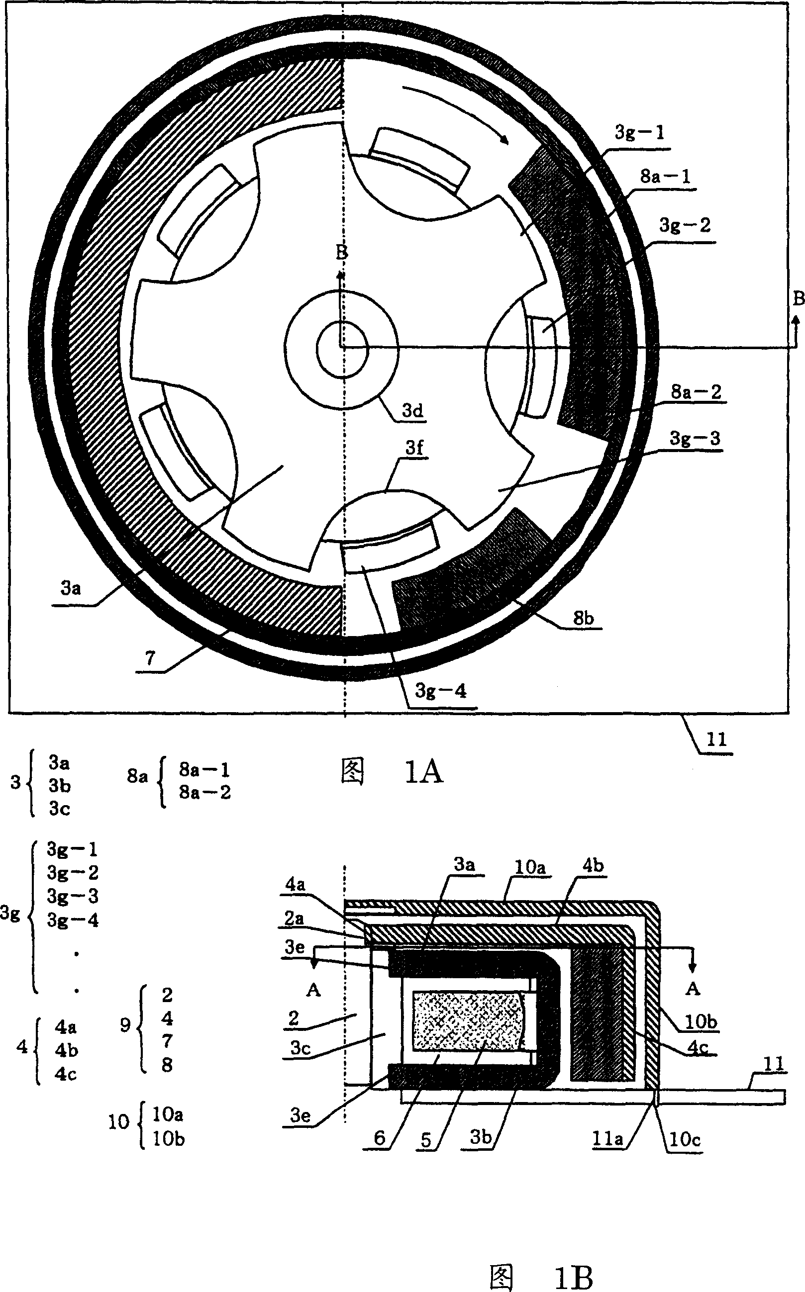
[0062] 1A and 1B are structural diagrams of a vibration motor applying an outer rotor type stepping motor according to an exemplary embodiment of the present invention. Fig. 1A is a sectional view along line A-A in Fig. 1B, and Fig. 1B is a sectional view along line B-B in Fig. 1A.

[0063] The vibration motor 1 includes a rotating shaft 2 and a rotor frame 4 having a third stator yoke 3c also serving as a bearing. The diameter of the rotating shaft 2 is, for example, 0.8 mm, and the outer diameter of the third stator yoke 3 c which also serves as a bearing is, for example, 1.8 mm.

[0064] The third stator yoke 3c, which also serves as a bearing, is made of an oilless metal magnetic material formed into a substantially cylindrical shape. (1) Most of the sides of the rotating shaft 2 are rotatably guided, (2) constitute a part of the magnetic circuit...

Embodiment 1

[0128] (Effect of Embodiment 1)

[0129] Since the outer rotor type incorporates eccentric weights in the same outermost rotating area as the magnets, the accommodation space for the eccentric weights can be shared with the magnets. Since the eccentric weight is arranged on the outermost side, the radius becomes long, strong vibration can be generated, and the part exposed to the outside can move. Also, since the stepping motor has no brushes, similar to other brushless motors, the need for maintenance is almost eliminated and its lifespan becomes longer.

[0130] In addition, when the control speed is synchronized with the input pulse, the amount of vibration can be adjusted linearly, and the braking time can be shortened.

[0131] Due to the single-phase, the excitation pulse current with alternating and reverse directions is input to the single-phase stator coil wound around the stator yoke. Since this coil has a single phase, it takes up less space and has a reduced thic...

no. 2 example

[0144] 5A and 5B are structural diagrams of an inner rotor type vibration motor according to a typical embodiment of the present invention. Figure 5A is along the Figure 5B The profile of C-C line, Figure 5B It is a sectional view taken along line D-D in FIG. 5A .

[0145] The bearing 12 is vertically arranged on the interface plate 21, just like the bearing shown in Embodiment 1, the cylindrical rotating shaft 19 is rotatably arranged on the bearing 12, the supporting body 22 is fixed to the rotating shaft 19, and the magnet 18 is arranged on The top of the support body 22. The magnets 18 include a rotor magnet 18a and an auxiliary pole magnet 18b. In the case of Embodiment 2, although the magnet 18 includes two magnets, the magnet may basically be constructed of one or more magnets. The magnetization, magnetic pole pitch, and the like of the rotor magnet 18 a and the auxiliary pole magnet 18 b are configured similarly to the case of Embodiment 1.

[0146] The stator i...


PUM


Abstract

A vibrating motor including a stepping motor in which control is simple, large vibration is generated, and drive torque can be efficiently generated, and a portable terminal apparatus using the same are provided. The vibrating motor includes a single-phase annular stator coil, a stator yoke disposed to surround the periphery of the single-phase annular stator coil and having pole teeth, an interface board fixing the stator yoke and having a wiring connected to the annular stator coil, plural arc-shaped magnets disposed to be opposite to the pole teeth and to be capable of rotating around a rotating shaft, and an eccentric weight capable of rotating around the rotating shaft.

Description

technical field [0001] The present invention relates to a vibration motor including a vibration mechanism for a vibrator such as a cellular phone, and a portable terminal device to which the vibration motor is applied. Background technique [0002] DC motors with brushes were used in the vibrators of the first cellular phones. Since semiconductor integration technology was not advanced at the time, it was extremely difficult to produce a circuit that also included a motor control circuit in a narrow portable phone, and a DC motor with brushes was widely used because it was low in price and rarely broke down. DC motors with brushes are classified into various types depending on where they are used or what they are used for. In a cylindrical type applied to a watch or the like, since the rotating surface of the shaft is in the thickness direction of the watch, reduction in thickness is difficult, and it is difficult to provide an external eccentric weight to obtain a vibratio...

Claims


Application Information

Patent Timeline
Patent Type & Authority Applications(China)
IPC IPC(8): H02K37/16
CPCH02K7/063B06B1/045H04M19/047H02K15/03H02K1/27
Inventor 松原真朗佐藤和明古田修梅原干雄
Owner MINEBEA MOTOR MFG
Why Eureka
Try Eureka