Slide palte deformed tooth stepless engagement adjustable gear

A technology of deformed teeth and slides, which is applied to gear transmissions, belts/chains/gears, V-shaped belts, etc., can solve the problems of low mechanical efficiency, narrow speed range, and low transmission power, and achieve low machining accuracy. Effect

Inactive Publication Date: 2006-03-29
王国斌
View PDF1 Cites 49 Cited by
  • Summary
  • Abstract
  • Description
  • Claims
  • Application Information

AI Technical Summary

Problems solved by technology

However, its manufacturing precision and installation precision are high, and more importantly, its transmission ratio is a fixed value, which cannot realize stepless transmission
At present, a large number of mechanical continuously variable transmissions use friction transmission, which generally has the following defects: 1. It is difficult to obtain ultra-low speed output, and the speed range is relatively narrow; 2. There are defects such as small transmission torque and low transmission power; 3. Carrying capacity Low, poor overload resistance and impact resistance; 4. High requirements for parts processing and lubrication, short life, complex structure and process, high manufacturing cost; 5. Large sliding rate, low mechanical efficiency; some still have pulsating output and power flow discontinuities
However: the current pulsating continuously variable transmission has several fatal weaknesses, which restrict its development in a wider field: the pulsation of the output makes it impossible to be used in occasions that require high output uniformity, although through multi-phase dislocation superposition and beyond The auxiliary clutch cooperates with the selectable flow filter to reduce the pulsation, and because of the inertia factor of the entire operating system and the overrunning effect of the overrunning clutch, the pulsation at the output end will be significantly smaller than the theoretical value, but this is only an appearance phenomenon, the actual power The current transmission is still output in the form of pulse intervals according to the theoretical value. The discontinuity of this power flow is a major factor causing the low efficiency of the pulsating continuously variable transmission; For stepping forward, the vibration caused by its unbalanced inertial force and moment of inertia will be significantly aggravated at high speeds, and the dynamic load it produces is still an important reason for low mechanical efficiency; 3. The overrunning clutch as the output mechanism is the only friction in the entire body The transmission component also has a series of corresponding defects of friction transmission, which is the weak link in the power chain of the entire mechanism. Its bearing capacity and impact resistance are relatively low, which restricts the development of pulsating continuously variable transmissions to high power, high efficiency and high speed.
4. The multi-phase structure set up to reduce the pulsation will cause too many repeated constraints in the system, which will cause the machine to be sensitive to errors and working environments, reduce efficiency, increase dynamic load, and increase the number of phases. , The debugging and installation process is complicated, the failure rate increases, and the cost increases

Method used


Image

  • Slide palte deformed tooth stepless engagement adjustable gear
  • Slide palte deformed tooth stepless engagement adjustable gear
  • Slide palte deformed tooth stepless engagement adjustable gear

Examples


Embodiment Construction

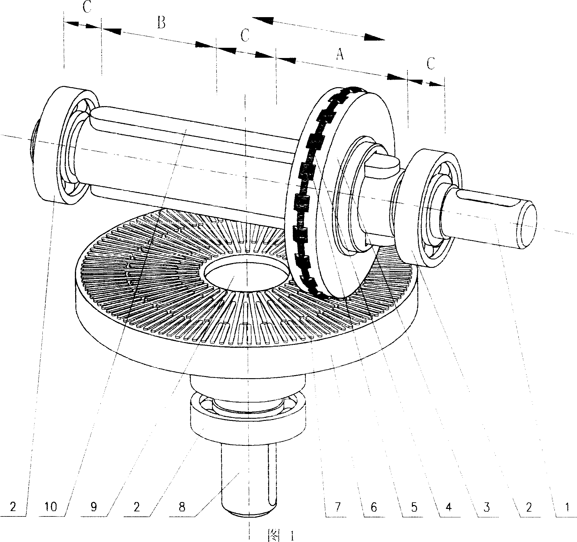
[0109] Cylindrical movable gear continuously variable transmission series

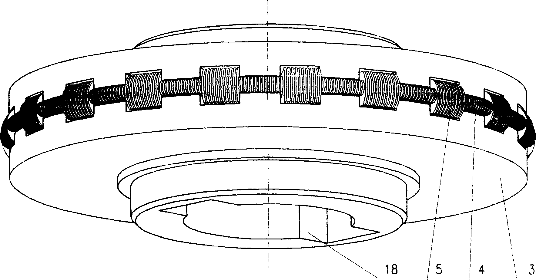
[0110] Figure 1. Structural diagram of cylindrical live gear continuously variable transmission figure 2 , Structural diagram of cylindrical movable gear

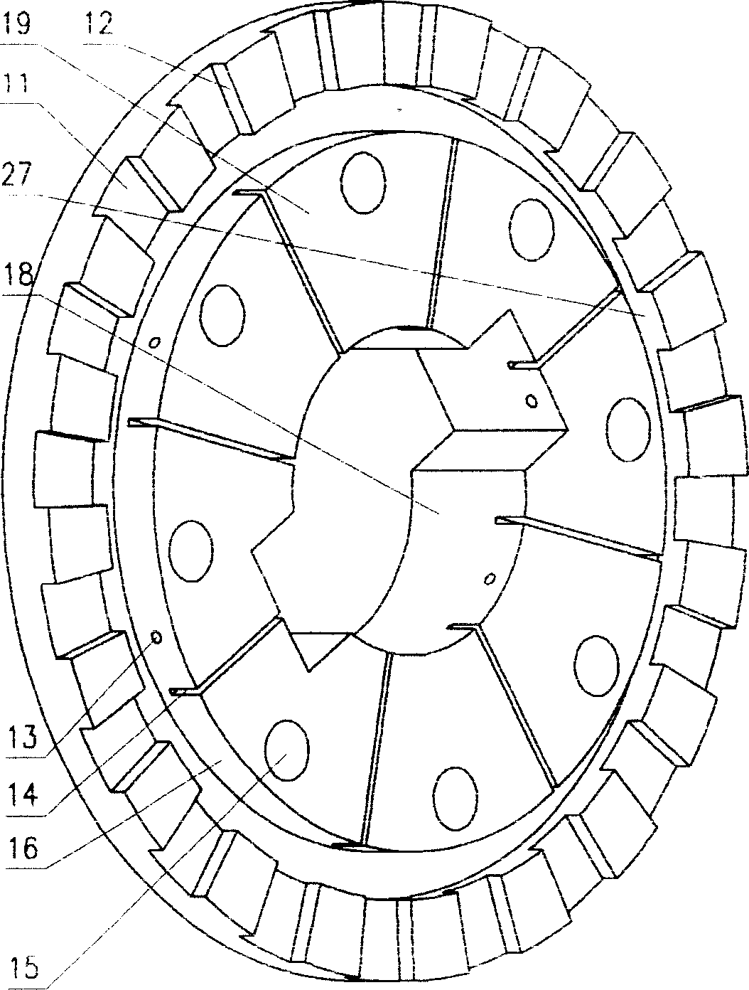
[0111] image 3 , Structural Diagram of Cylindrical Live Gear Wheel Figure 4, Structural Diagram of Sliding Plate for Cylindrical Live Gear

[0112] Figure 5, Internal structure diagram of cylindrical movable gear Fig. 6, Plan view of internal structure of cylindrical movable gear

[0113] As shown in the figure: the input shaft is connected to the cogged wheel, and the movable gear is connected to the output shaft through a guide key or a spline, which can freely move axially while transmitting torque, and the meshing radius with the cogged wheel can be changed steplessly. Stepless speed change (in Fig. 1: A, B, C represent respectively: forward gear zone, reverse gear zone, neutral gear zone).

[0114] The structure of the cylindrical liv...


PUM


Abstract

The oscillating tooth gear is designed according to the ''sliding vane stepless deformation principle'', its working surface is made up by coinciding lots of sliding vanes (sliding needles), it can utilize sliding vane free stepless slippage to form any shaped meshed tooth profile. Because the slippage direction of sliding vane is different from its stress direction, the sliding vane can be freely deformed with current meshed tooth profile, and the stress direction when the power is trans ferred is perpendicular to free slippage direction or its included angle is in the equivalent frictional angle, so that said sliding vane has the self-locking property, and when the stress is borne by it, it does not change tooth profile form, all the sliding vanes can be formed into an integrated elastic closed ring, therefore it has strong bearing capacity and high transmission efficiency.

Description

technical field [0001] The invention belongs to the technical fields of gear transmission and mechanical stepless transmission design and manufacture. Background technique [0002] Gear transmission is the most widely used transmission mechanism in machinery at present. It has the following advantages: it can ensure a constant ratio of instantaneous angular velocity between the two gears; The peripheral speed range is relatively large, from very low to as high as 300m / s; the transmission efficiency is high, and the primary transmission efficiency is as high as 98~99%; the service life is relatively long. However, its manufacturing precision and installation precision are high, and more importantly, its transmission ratio is a fixed value, which cannot realize stepless speed change. At present, a large number of mechanical continuously variable transmissions use friction transmission, which generally has the following defects: 1. It is difficult to obtain ultra-low speed out...

Claims


Application Information

Patent Timeline
Patent Type & Authority Applications(China)
IPC IPC(8): F16H3/42F16H61/04
CPCF16H55/17H01L2924/0002F16G1/28F16H55/54F16H3/426F16G5/16F16H55/56F16H3/423F16H9/24F16H55/171F16H3/002H01L2924/00F16H55/26F16H3/00
Inventor 王国斌
Owner 王国斌
Why Eureka
Try Eureka