Dynamic voltage mode phase interpolation circuit suitable to phase locked loop of each annular oscillation

A technology of phase interpolation and dynamic voltage, applied in automatic power control, electrical components, etc., can solve problems such as wasting chip area and increasing total power consumption

Inactive Publication Date: 2006-04-19
FUDAN UNIV
View PDF0 Cites 6 Cited by
  • Summary
  • Abstract
  • Description
  • Claims
  • Application Information

AI Technical Summary

Problems solved by technology

And this will waste a lot of chip area, an

Method used


Image

  • Dynamic voltage mode phase interpolation circuit suitable to phase locked loop of each annular oscillation
  • Dynamic voltage mode phase interpolation circuit suitable to phase locked loop of each annular oscillation
  • Dynamic voltage mode phase interpolation circuit suitable to phase locked loop of each annular oscillation

Examples


Embodiment Construction

[0027] Attached below Figure 1-8 The present invention is described in detail.

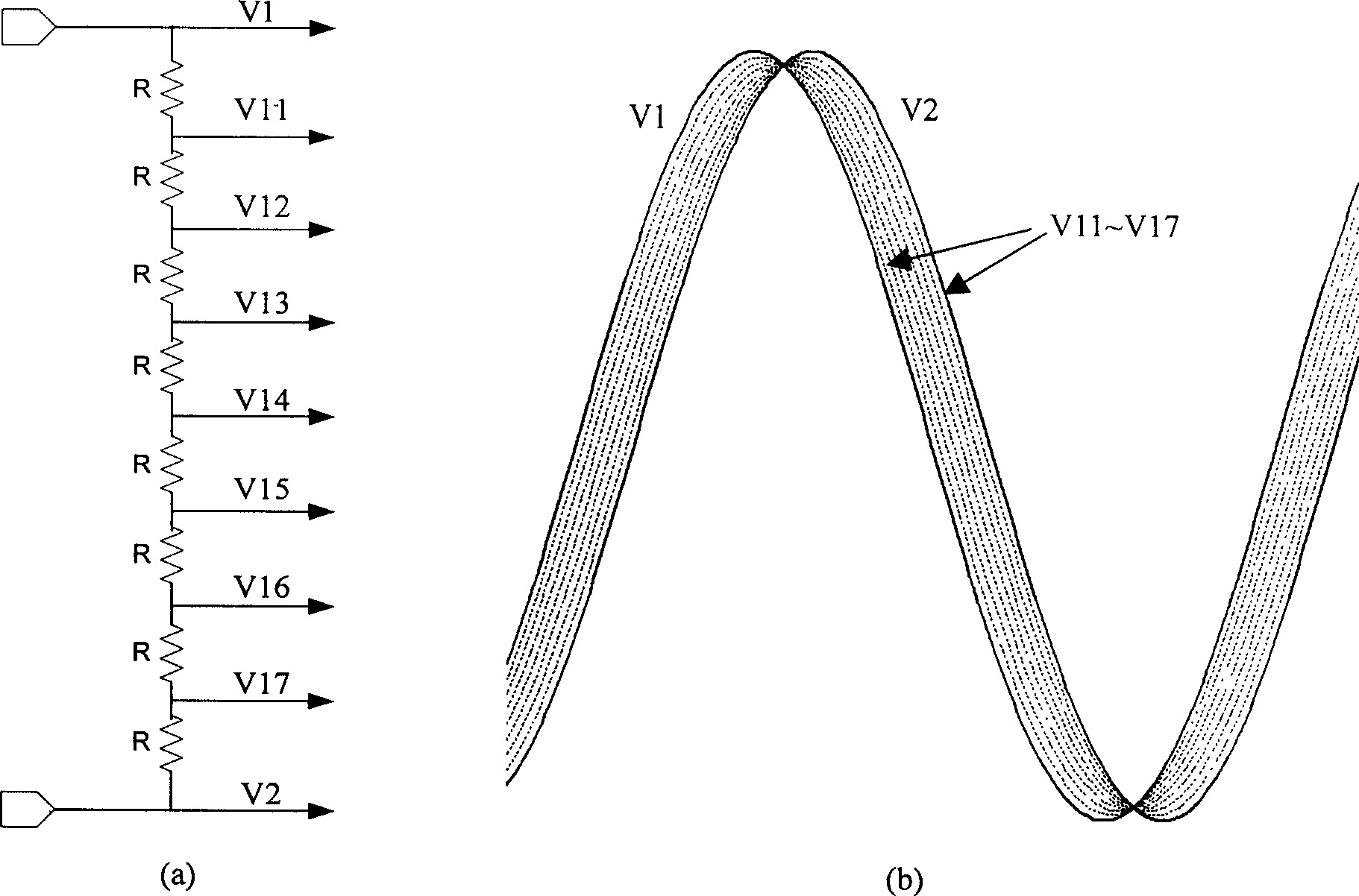
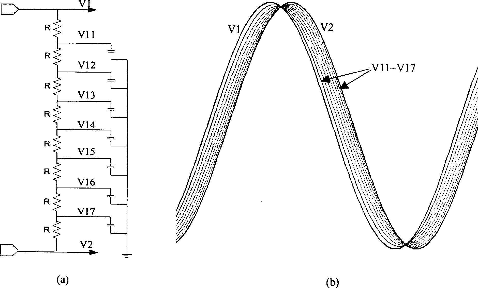
[0028] figure 1 It is a schematic diagram of the principle of resistance voltage division and a sine wave input and output waveform. What is described in the figure is the most basic and ideal situation, where the voltages V1 and V2 are used as ideal input signals, and each output is not connected to the load. At most of the time (excluding the distortion near the peak value of the waveform), the value of V1-V2 is a constant, and the current caused by the voltage difference all flows through the series voltage dividing resistor. In order to achieve the same ΔV for adjacent output voltages (which can be converted into the same time delay at the same slew rate, that is, the phase difference), the resistor string can be an average resistor, and the interpolation result has nothing to do with the absolute value of the resistor.

[0029] But in all applications it is impossible for the output to b...


PUM


Abstract

The circuit consists of two pieces of predriver, resistance string in use for voltage division, two load capacitances in use for lowering slew rate of input clock, and clock reshapping drive connected each other through circuit. Number of resistance in string, number of reshapping drive is equal to number of phase interpolation. The two load capacitances are connected between two pieces of predriver and two ends of resistance string respectively. Reshapping drives are connected to each resistance in parallel. Thus, flatten out edge is adjusted back to original shape; and circuit in next stage is driven. Advantages are: reduced chip area and weakened interference of power supply and signal crosstalk.

Description

technical field [0001] The invention belongs to the technical field of integrated circuits, and in particular relates to a voltage mode phase interpolation circuit applied in a frequency synthesizer, in particular to a circuit design for superfine clock output using dynamic voltage mode phase interpolation. Background technique [0002] The clock circuit is an essential and important part of almost all system chips. It mainly realizes the functions of frequency synthesis, clock recovery, time delay and noise suppression through the phase-locked loop of the core circuit. [0003] The clock recovery circuit using the phase-locked loop mainly has two implementation schemes: the full analog circuit and the combination with the digital signal processing method. The noise suppression ability of the clock recovery circuit using the analog scheme is not strong, and the process portability is also poor. At the same time, in order to improve the phase detection speed of the phase cap...

Claims


Application Information

Patent Timeline
IPC IPC(8): H03L7/08
Inventor 陆平叶凡任俊彦郑增钰
Owner FUDAN UNIV
Why Eureka
Try Eureka