Method and apparatus for using optical tweezers to manipulate materials

A technology of equipment and light beams, applied in the direction of biochemical equipment and methods, special-purpose bioreactors/fermenters, optics, etc.

Inactive Publication Date: 2006-04-26
UNIVERSITY OF CHICAGO
View PDF1 Cites 0 Cited by
  • Summary
  • Abstract
  • Description
  • Claims
  • Application Information

AI Technical Summary

Problems solved by technology

[0008] In special cases, however, laser-induced damage may be desirable

Method used


Image

  • Method and apparatus for using optical tweezers to manipulate materials
  • Method and apparatus for using optical tweezers to manipulate materials
  • Method and apparatus for using optical tweezers to manipulate materials

Examples


Embodiment Construction

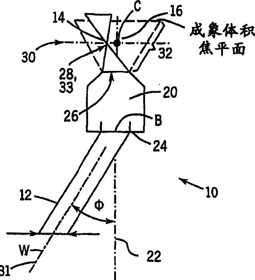
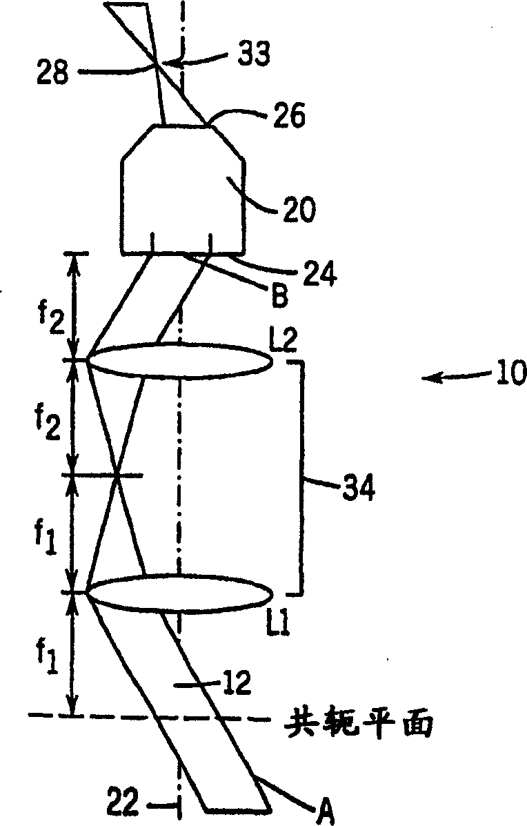
[0032] In order to better understand the improvement of the present invention, figure 1 and 2 Several methods and systems of the prior art are described. exist figure 1 In the optical tweezer system 10 of , the optical gradient force is generated due to the controllable manipulation of small dielectric particles 14 dispersed in a medium 16 using a single beam 12, wherein the medium has a refractive index n m smaller than the refractive index of the particle 14. The fundamental properties of optical gradient forces are well known, and of course in general terms the principle can manipulate reflection, absorption and low dielectric constant particles. Any of these techniques may be implemented in the description of the improvements of the invention described below, and the terms optical clamp, optical trap and optical gradient force trap will be used for description hereinafter.

[0033] The optical clamp system 10 is applied by using a light beam 12, such as a laser beam or...


PUM


Abstract

The present invention relates to methods and apparatus for manipulating materials using light beams. The present invention provides methods and apparatus for controlling the formation of optical trap arrays and particle arrays using light in the visible portion of the spectrum. The method and device have a laser and a time-varying diffractive optical element, can dynamically control the optical trap array, thereby controlling the particle array, and have the ability to use multiple optical traps to manipulate special objects. By avoiding wavelengths associated with strong absorption in the underlying material, creating optical traps with continuous wave lasers, optimizing the efficiency of each trap, and trapping the extended sample at multiple points, the extent of detrimental nonlinear optical effects can be minimized minimum.

Description

[0001] This application is a divisional application of a patent application with an application date of October 7, 2003, an application number of 02808941.3 (PCT / US 02 / 13307), and a title entitled "Equipment for Manipulating Materials Using Optical Tweezers". [0002] This work was made with the support of the U.S. Government through a GAANN Fellowship from the Department of Education under Contract No. DMR-9730189 to the National Science Foundation under Contract No. invention. The US Government also has certain rights in this invention. technical field [0003] In general the present invention relates to methods and apparatus for controlling an optical trap or optical tweezer. More specifically, the present invention relates to optical tweezers formed using visible light that can be used to manipulate a variety of light-sensitive materials, such as living biological materials, without causing significant damage or deleterious effects to the material being studied or manipul...

Claims


Application Information

Patent Timeline
Patent Type & Authority Applications(China)
IPC IPC(8): G02B21/32G02B27/42C12M1/00C12N1/00
CPCG02B21/32G02B27/1086G02B27/42G02B27/4244G02B27/425
Inventor 戴维·G·格里尔埃里克·R·迪弗雷纳詹妮弗·E·库尔蒂斯布赖恩·A·考斯
Owner UNIVERSITY OF CHICAGO
Why Eureka
Try Eureka