Oil-heating and heat-recovery type dyeing machine
A heat recovery type, oil heating technology, applied to heat exchanger types, lighting and heating equipment, indirect heat exchangers, etc., can solve problems such as wasting energy, increase heating efficiency, improve heat exchange rate, and improve cooling effect Effect
- Summary
- Abstract
- Description
- Claims
- Application Information
AI Technical Summary
Problems solved by technology
Method used
Image
Examples
Embodiment 1
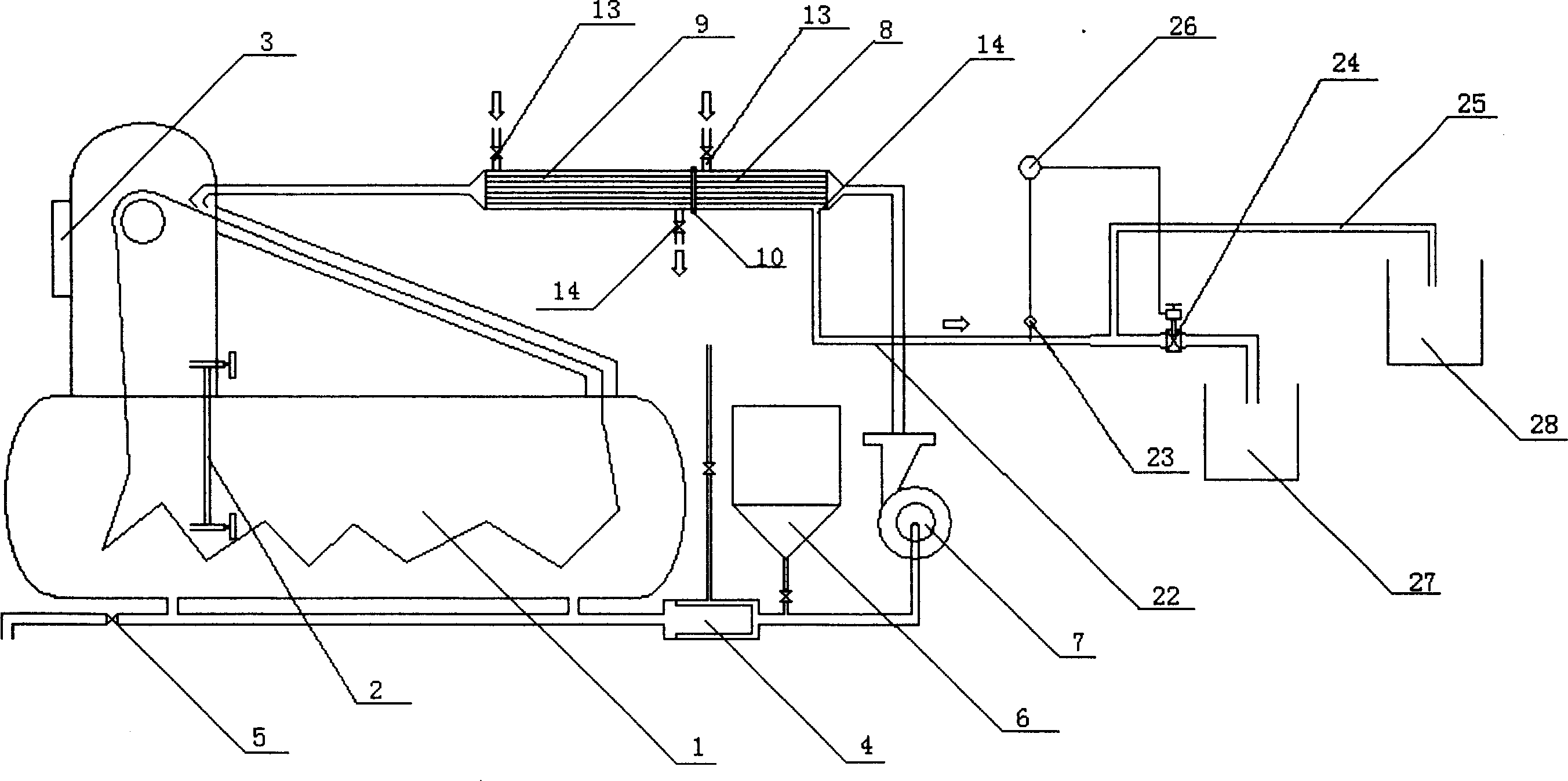
[0022] Embodiment 1: as figure 1 As shown, the present invention comprises a cloth dyeing cylinder 1, in which a water level pipe 2 is provided, and a cloth inlet and outlet 3 is provided on the upper side thereof, and the cloth dyeing cylinder 1 is respectively connected with the filter 4, The dye liquor supply and drainage valve 5 is connected, the other end of the filter 4 is connected with the feeding barrel 6 and the circulating water pump 7 through a pipeline, and the water that is combined into one through the flange 10 is connected between the dyeing cloth cylinder 1 and the circulating water pump 7. Cooling exchanger 8 and oil heating exchanger 9 .
[0023] Such as Figure 5 As shown, the water cooling exchanger 8 and the oil heating exchanger 9 have the same structure, and both include a cylinder 16, which is provided with layered heat receiving tubes 11, and the heating tubes 11 can be metal round tubes or special-shaped tubes with high heat transfer coefficients. ...
Embodiment 2
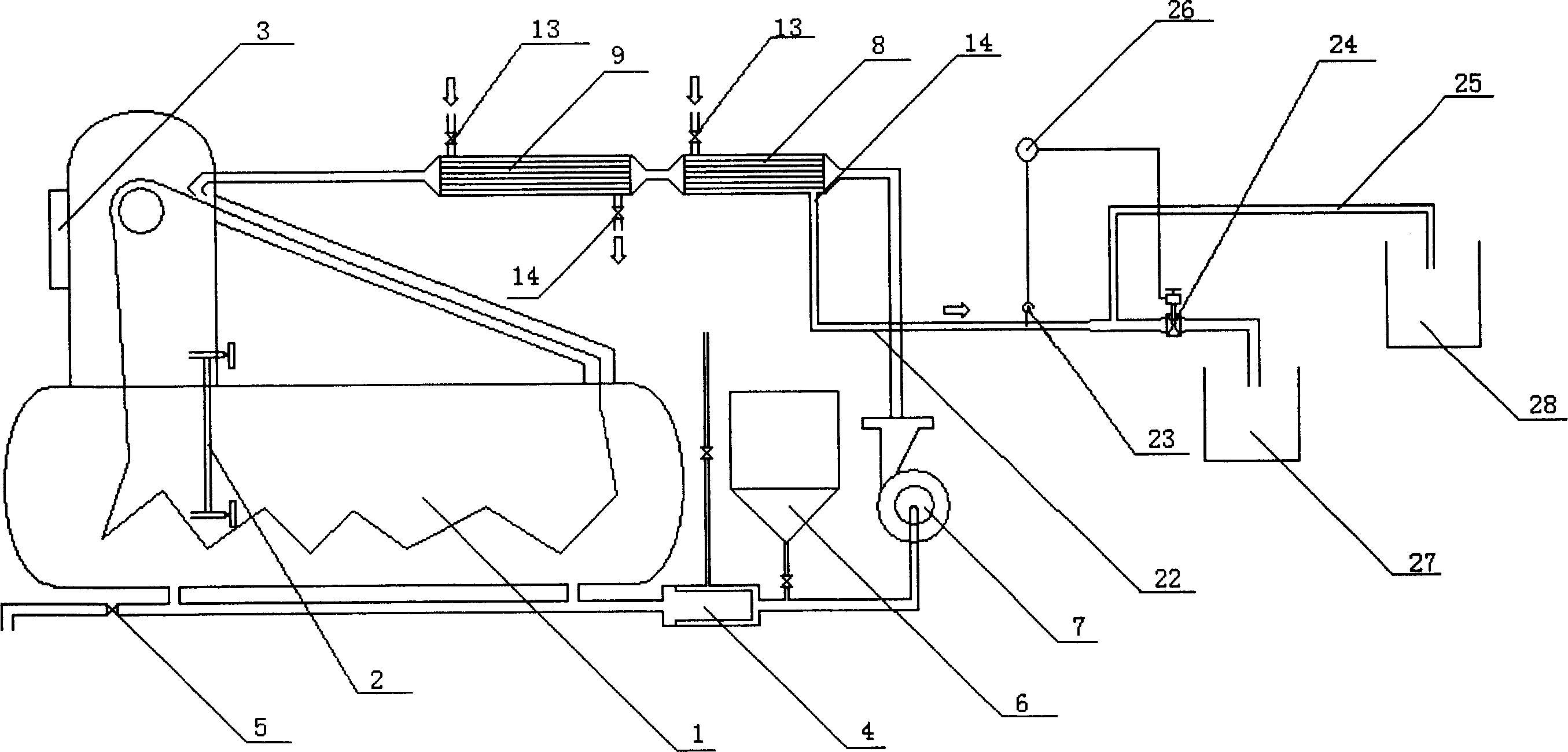
[0029] Embodiment 2: The basic structure of this embodiment is the same as that of Embodiment 1, except that a water cooling exchanger 8 and an oil heating exchanger 9 connected in series are connected between the dyeing cloth cylinder body 1 and the circulating water pump 7, such as figure 2 , Image 6 shown. Its working process is with embodiment 1.
Embodiment 3
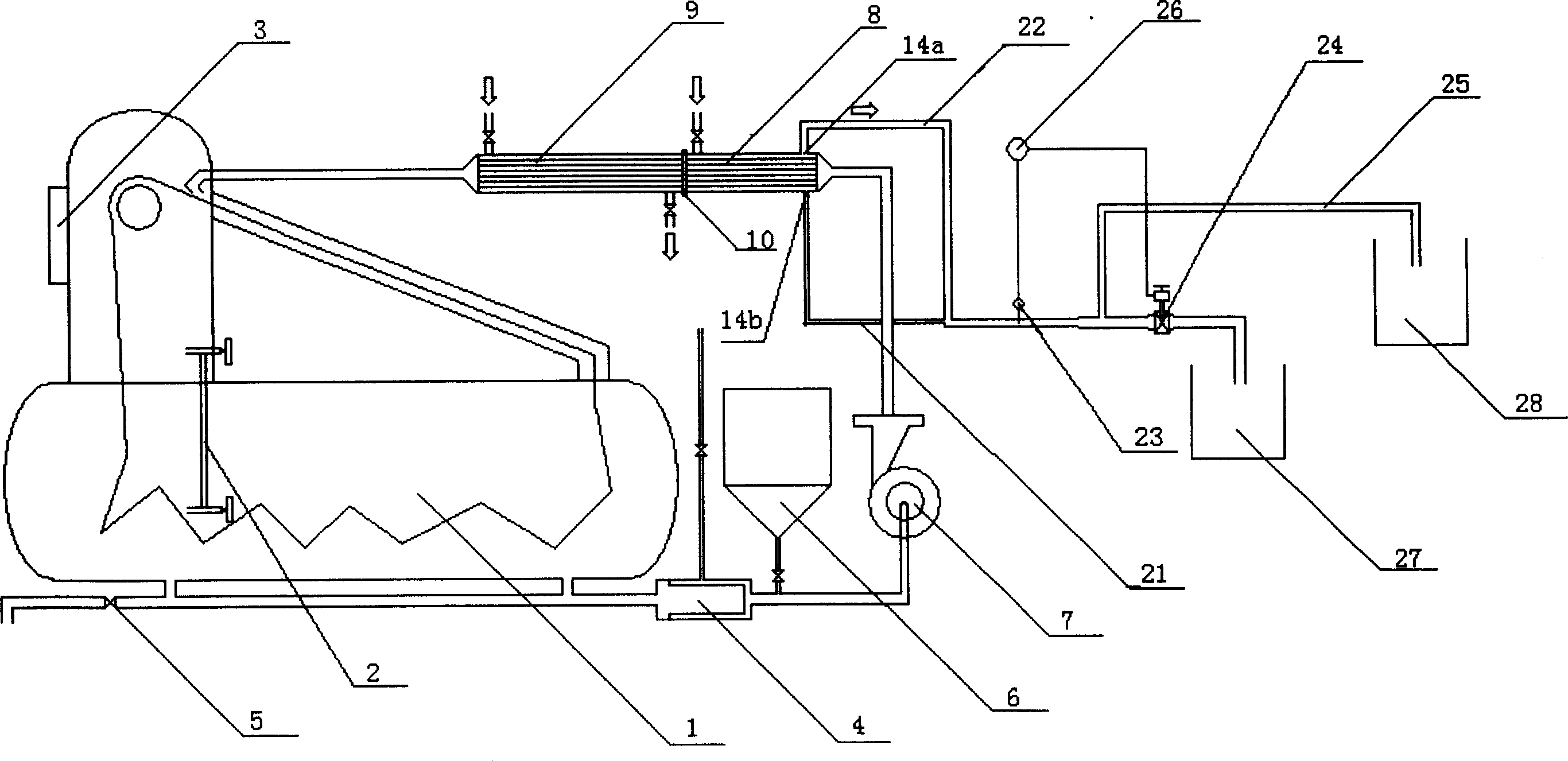
[0030] Embodiment 3: The basic structure of this embodiment is the same as that of Embodiment 1, except that the outlet 14 provided on the cylinder 16 of the water cooling exchanger 8 can be divided into a main outlet 14a and a secondary outlet 14b, wherein the main outlet 14a Located above the cylinder 16, the auxiliary outlet 14b is located below the cylinder 16, and the diameter of the auxiliary outlet 14b is smaller than that of the main outlet 14a. The main outlet 14a is connected with a pipe 22 , the auxiliary outlet 14b is connected with a pipe 21 , and the other end of the pipe 21 communicates with the pipe 22 . Such as image 3 , Figure 5 shown. The working process of this embodiment is the same as that of Embodiment 1, the difference is that when the cooling water is discharged, it can flow out from the main outlet 14a with a large flow rate, and flow out from the auxiliary outlet 14b with a small flow rate, and then divert to the diversion device after being aggr...
PUM
 Abstract
Description
Claims
Application Information
 - R&D
- Intellectual Property
- Life Sciences
- Materials
- Tech Scout
- Unparalleled Data Quality
- Higher Quality Content
- 60% Fewer Hallucinations
Browse by: Latest US Patents, China's latest patents, Technical Efficacy Thesaurus, Application Domain, Technology Topic, Popular Technical Reports.
© 2025 PatSnap. All rights reserved.Legal|Privacy policy|Modern Slavery Act Transparency Statement|Sitemap|About US| Contact US: help@patsnap.com


