

Coil, induction motor for motor and its stator manufacturing method
A technology of induction motors and electric motors, applied in the field of electric motors, can solve problems such as shortening the life of electric motors, and achieve the effects of improving efficiency, reducing production costs, and saving man-hours
- Summary
- Abstract
- Description
- Claims
- Application Information
AI Technical Summary
Problems solved by technology
Method used
Image

Examples
Embodiment 1
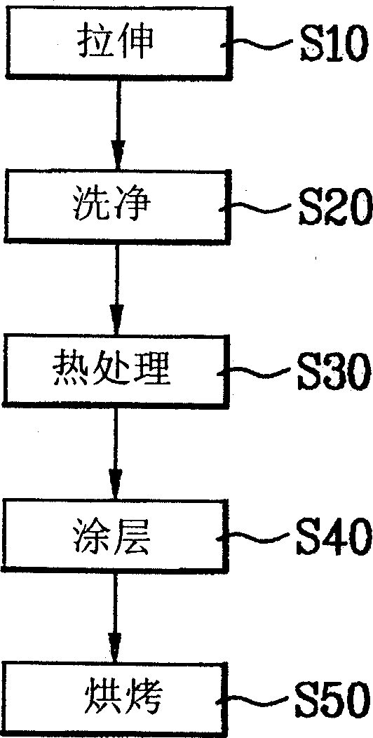
[0036] figure 1 It is a flow chart of the manufacturing process of the coil for the motor of the present invention. The motor coil of the present invention includes: a core wire with electrical conductivity and a ceramic insulating film formed on the surface of the core wire; the ceramic insulating film is used to increase the maximum allowable temperature of the motor coil.
[0037] Depend on figure 1 It can be seen that the manufacturing process of the coil for the motor of the present invention includes the following stages:
[0038] Stretching stage S10: first, the core wire used for the motor coil is stretched by wire drawing process, so that the diameter of the core wire reaches the specified standard;
[0039] Cleaning stage S20: Then, remove impurities on the surface of the core wire after the stretching stage S10;
[0040] Heat treatment stage S30: Then, the core wire after the cleaning stage S20 is heated to a certain temperature and then slowly cooled to anneal i...
Embodiment 2
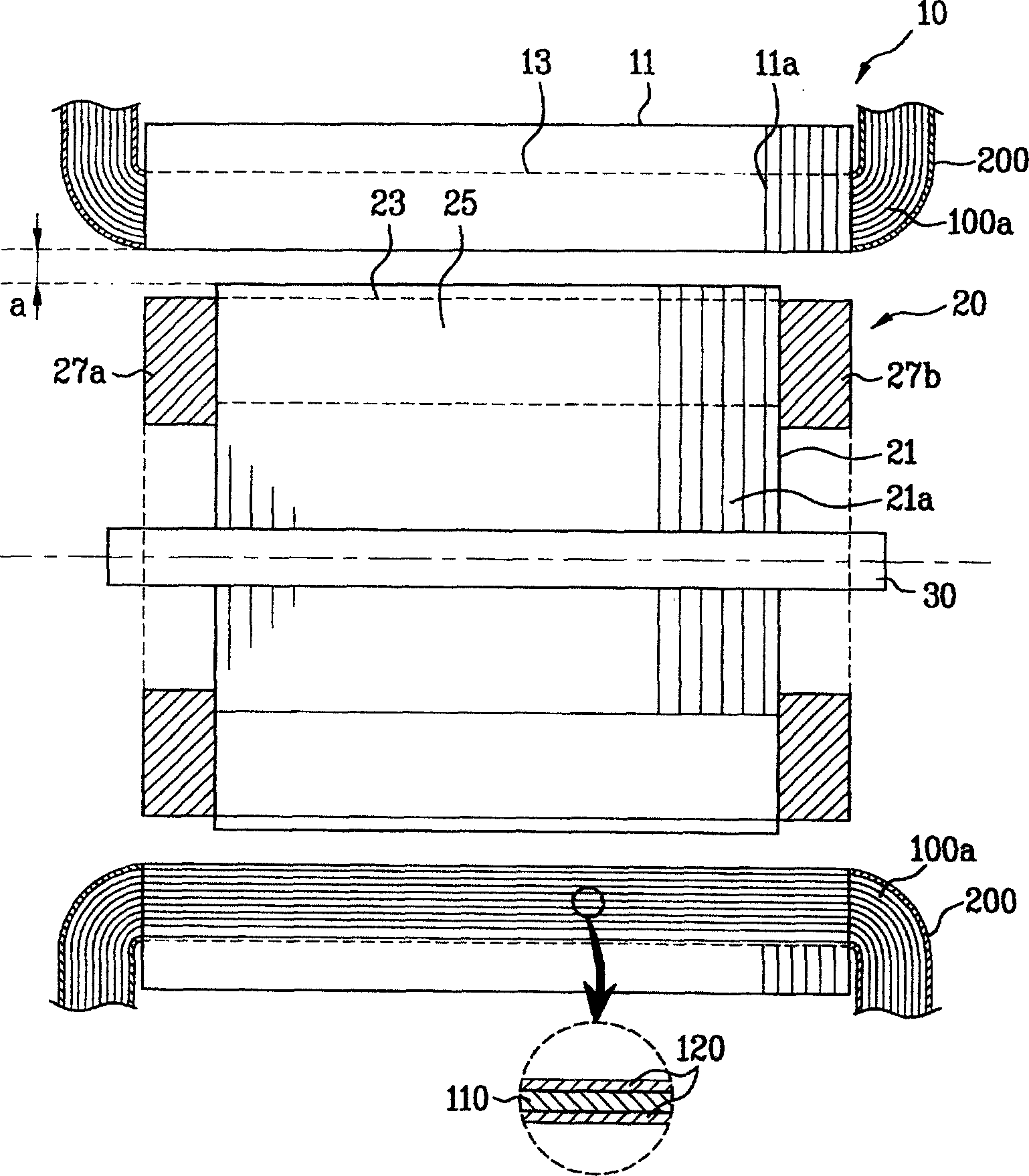
[0048] Refer below figure 2 The induction motor of the present invention is described in detail:
[0049] figure 2 It is a schematic cross-sectional structure diagram of the induction motor of the present invention. Such as figure 2 As shown, the induction motor of the present invention includes: a stator 10, a rotor 20, and a rotating shaft 30; There is a gap a between them; the rotating shaft 30 is pressed into the center of the rotor 20 to transmit the rotating force of the rotor.
[0050] The stator 10 includes: a stator coil that generates a rotating magnetic field and a magnetic stator core 11 that forms the passage of the magnetic field lines of the rotating magnetic field when the AC power is turned on; the stator core 11 is composed of several circular silicon steel sheets 11a It is stacked, and the inner peripheral surface of the stator core 11 is uniformly formed with several stator coil slots 13 along the axial direction. Viewed from the end face of the stat...
Embodiment 3
[0059] The manufacturing method of the stator provided with an insulating film on the coil end turns of the stator coil in the above-mentioned induction motor is described below:
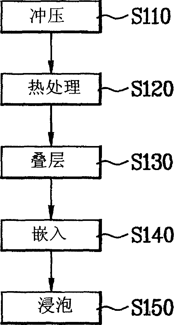
[0060] image 3 It is a flow chart of the manufacturing process of the induction motor stator of the present invention. Depend on image 3 As can be seen, the manufacturing method of the stator of the induction motor of the present invention comprises the following stages:
[0061] Stamping stage S110: first, use a mold to stamp and form several stator coil slots 13 on the inner peripheral surface of the silicon steel sheet 11a;
[0062] Heat treatment stage S120: performing annealing heat treatment on the silicon steel sheet 11a after the stamping stage S110, heating the silicon steel sheet 11a to a certain temperature, and then cooling it; in order to eliminate the residual mechanical stress in the silicon steel sheet 11a and restore its mechanical properties;
[0063] Lamination stage S130: La...
PUM
 Abstract
Description
Claims
Application Information