

Magnetic core for high frequency and inductive component using same
A technology of inductive components and magnetic cores, applied in the field of inductive components and high-frequency magnetic cores, can solve the problems of restrained industrial application promotion, high cost, and insufficient loss reduction
- Summary
- Abstract
- Description
- Claims
- Application Information
AI Technical Summary
Problems solved by technology
Method used
Image

Examples
Embodiment 1~36, comparative Embodiment 1~13
[0054] First, as a powder preparation step, pure metal element materials including Fe, Si, B, Nb, and substitute elements are weighed to obtain a predetermined composition. By using these materials, various soft magnetic alloy powders are prepared by commonly used water atomization. Note here that mischmetal (misch) is a mixture of rare earth metals. Here, a mixture of 30% La, 50% Ce, 15% Nd and the balance of one or more other rare earth elements is used.
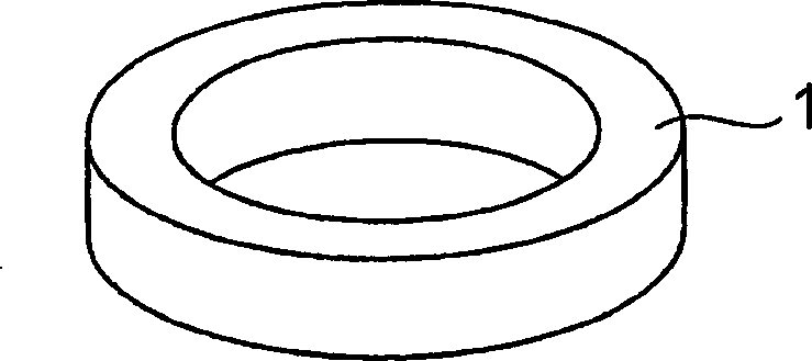
[0055] Next, as a molded body preparation step, various alloy powders were divided into alloy powders having a powder size of 45 um or less. Subsequently, a silicone resin as a binder was mixed in at 5% by mass. Then, by using the grooved and outer diameter φ 外 =27mm, internal diameter φ 内 = 14mm die head, by applying 14.7 x 10 at room temperature 8 Various molded bodies were formed under a pressure of Pa such that the height of the molded body was equal to 5 mm.
[0056] In addition, various molded bodies are subjec...
Embodiment 37
[0065] Prepared by water atomization with (Fe 0.8 Ni 0 co 0.2 ) 75 Si 4 B 20 Nb 1 composed of alloy powders. The powder thus obtained was classified into a powder having a size of 75 μm or less. XRD measurement was carried out, and a broad peak characteristic of a glass phase was confirmed. Next, DSC thermal analysis was performed to measure the glass transition temperature and the crystallization temperature, thereby confirming that ΔTx was 35K. Then, the powder was heat-treated in atmospheric air at 450°C below the glass transition temperature for 0.5 hours, thereby forming oxides on the powder surface. Next, the powder was mixed with 10%, 5%, 2.5%, 1% and 0.5% silicone. These powders were molded under three conditions of room temperature, 150°C above the softening temperature of the resin, and 550°C in the supercooled liquid temperature range of the metallic glass powder by using a φ27×φ14 die. The powder filling ratio, the magnetic flux density measured by DC mag...
Embodiment 38
[0069] In Example 38, by water atomization prepared with Fe 73 Si 7 B 17 Nb 2 Zn 1 composed of alloy powders. Subsequently, the powder thus obtained was divided into powders having a particle size of 75 μm or less. Then, XRD measurements were performed to confirm the broad peaks characteristic of the glass phase. In addition, DSC thermal analysis was performed to determine the glass transition temperature and crystallization temperature, thereby confirming that the glass transition onset temperature range ΔTx was 35K. Then, the powder was maintained and heat-treated for 0.5 hours in atmospheric air and at a temperature of 450C lower than the glass transition temperature to form oxides on the powder surface.
[0070] Next, the powder was mixed with 10%, 5%, 2.5%, 1% and 0.5% by mass of silicone resin as a binder. By using an external diameter φ 外 =27mm×internal diameter φ 内 = 14 mm grooved die, the powders were tested at three different temperature conditions, namely a...
PUM
| Property | Measurement | Unit |
|---|---|---|
| Density | aaaaa | aaaaa |
| Density | aaaaa | aaaaa |
| Density | aaaaa | aaaaa |
Abstract
Description
Claims
Application Information