Damper

A damper and damping cavity technology, used in liquid shock absorbers, building components, elastic suspensions, etc., can solve the problems of high starting resistance, damper damage, heat generation, etc., and achieve low starting resistance, stable performance, and structural simple effect

Active Publication Date: 2006-06-14
尹学军 +1
View PDF0 Cites 34 Cited by
  • Summary
  • Abstract
  • Description
  • Claims
  • Application Information

AI Technical Summary

Problems solved by technology

However, due to structural reasons, it has inherent defects: 1) Due to the static friction and sliding friction between the seal and the piston rod, and the piston and the damping cylinder, the starting resistance is relatively large, and the damping force has a poor correlation with the speed when the amplitude is small. , resulting in complex theoretical calculations and large errors; 2) A tight seal must be used, but the seal is easy to wear or age. Once the seal fails, the pressure difference cannot be established, and the damping performance will be lost rapidly; 3) The structure of the parts is complex and the number is large 1. The processing precision is high, so the cost is high; 4) The damping performance is sensitive to the processing precision an

Method used


Image

  • Damper
  • Damper
  • Damper

Examples


Embodiment 1

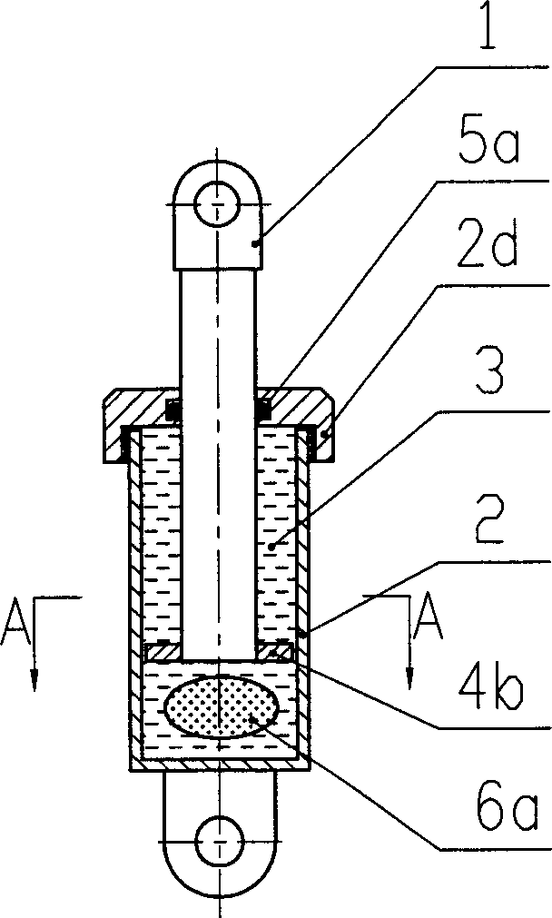
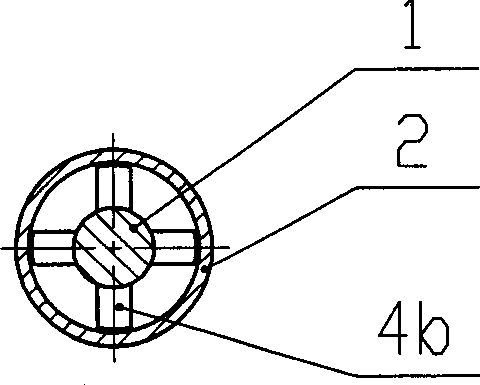
[0037] see figure 1 , 2 , which includes a moving body 1 and a cylinder body 2. The moving body 1 is partially located in the cylindrical cylinder body 2 and can move axially relative to the cylinder body 2. A damping chamber extending axially is arranged in the cylinder body. The damping chamber is filled with a viscous damping liquid 3, which is modified emulsified asphalt in a viscous liquid state at normal temperature. The moving body 1 is composed of a cylindrical moving blade, which is located in the damping chamber and connected with the damping chamber The walls form a shear cavity whose radial dimension is much smaller than its axial dimension. The end of the cylinder block is provided with a cylinder head 2a, which cooperates with the sliding guide of the moving blade, and the sliding sealing ring 5 is embedded in the cylinder head, and the end of the moving blade is fixed with a sliding guide block 4b, which is in the shape of a cross, allowing the damping liquid t...

Embodiment 2

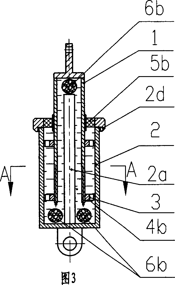
[0041] Referring to accompanying drawings 3 and 4, compared with embodiment 1, a cylindrical stationary vane 2a is provided in the center of the cylinder body 2, and the damping chamber is changed into an annular damping chamber. Correspondingly, the moving blade of the moving body 1 is tubular , the moving blade is located in the damping chamber, and forms a shearing chamber with the wall of the damping chamber and the stationary vane 2a. The damping chamber and the shearing chamber are filled with methyl silicone oil, and the transverse dimension of the shearing chamber is much smaller than its axial dimension. The lower part of the damping chamber is provided with an annular elastic compensator 6b, and the damping chamber at the top of the moving body is provided with an elastic compensator 6b. The elastic compensator 6b is an elastic foamed polyurethane with an airtight elastic layer on the outside.

[0042] Compared with Example 1, the moving blade of this embodiment has t...

Embodiment 3

[0047] See attached Figure 7 , 8 , compared with embodiment 2, the stationary blade in the damping chamber in the cylinder body 2 is a garden tubular shape 2c, and the moving body 1 is composed of 2 circular tubular moving blades, forming 3 concentric shearing chambers, and the damping chamber The lower part is provided with an annular elastic compensation body 6b, and the elastic compensation body is an elastic foamed polyurethane with an airtight elastic layer on the outside. There is a compensation chamber on the top of the moving body, and an airtight elastic film 6c is arranged in the compensation chamber, one side of which is filled with compressed air, and the other side is filled with damping liquid, which communicates with the damping chamber to compensate for the volume change of the damping chamber ; In order to increase the viscous resistance, the end of the inner moving blade is also provided with a flanging type spoiler ring piece.

[0048] In this embodiment,...


PUM


Abstract

The invention relates to a vibration-absorbing dissipative damper, which comprises a cylinder body and a moving body. The moving body is partly located in the cylinder. At least one cavity extending along the shaft is disposed in the cylinder. Viscous damping liquid is filled in the cavity and formed damping cavity. The moving body is made up of moving vanes disposed in the damping cavity. A shearing cavity is formed via the moving vanes and the damping cavity wall.

Description

technical field [0001] The invention relates to a vibration control device, a damper, especially a shock absorber for a vehicle suspension system and a vibration reduction and energy consumption damper for a building structure. Background technique [0002] Damper is a widely used basic component of vibration control, which is used for vibration reduction, buffering and energy dissipation of machinery, vehicles, bridges and building structures. [0003] The common damper is a hydraulic cylinder type. The piston only moves in the axial direction relative to the cylinder. It is called a single-axis damper. It is composed of a moving body, a moving body rod, a cylinder body and a seal. The moving body is generally cylindrical. The moving body is provided with a number of small holes or an appropriate radial gap is left between the cylinder and the moving body. When the moving body moves relative to the oil cylinder, the liquid sealed in the moving bod...

Claims


Application Information

Patent Timeline
IPC IPC(8): F16F9/16B60G13/08E04B1/98F16F9/53
CPCF16F9/18
Inventor 尹学军
Owner 尹学军
Why Eureka
Try Eureka