Micro band superwide band antenna

An ultra-wideband antenna and microstrip technology, applied in antennas, radiating elements, electrical components, etc., can solve the problems of increasing product cost, difficulty in integration, and low yield rate, and achieve strong practicability, easy integration, and high-quality products rate effect

Inactive Publication Date: 2006-06-14
PEKING UNIV
View PDF1 Cites 9 Cited by
  • Summary
  • Abstract
  • Description
  • Claims
  • Application Information

AI Technical Summary

Problems solved by technology

[0007] But so far, there are still many challenges for UWB antennas
First, the cost is high, such as the use of precious metal materials and substrates, which increases the cost of ultra-broadband products, makes it difficult to promote products on a large scale, and makes it difficult for ordinary consumers to accept
Second, the processing technology is complicated. On the one hand, the yield rate is low, and on the other hand, the cost of the product is increased.
Third, the volume is large. A common feature of the current ultra-wideband antenna solutions is that the antenna products are too large, and many surface areas are larger than 30cm×30cm, which is difficult to integrate, and the excessive volume increases the cost.

Method used


Image

  • Micro band superwide band antenna
  • Micro band superwide band antenna
  • Micro band superwide band antenna

Examples


Embodiment 1

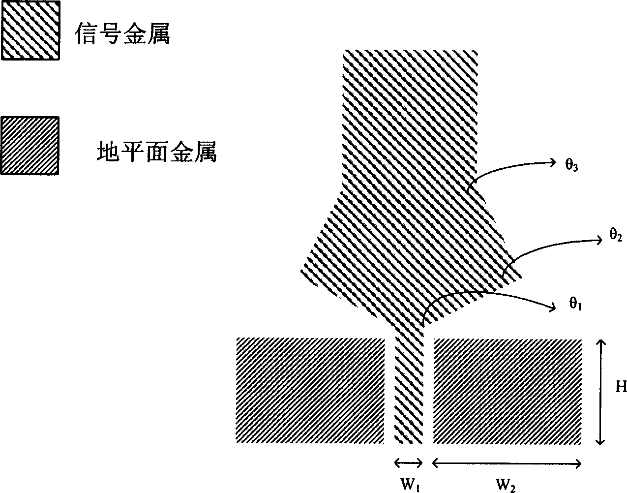
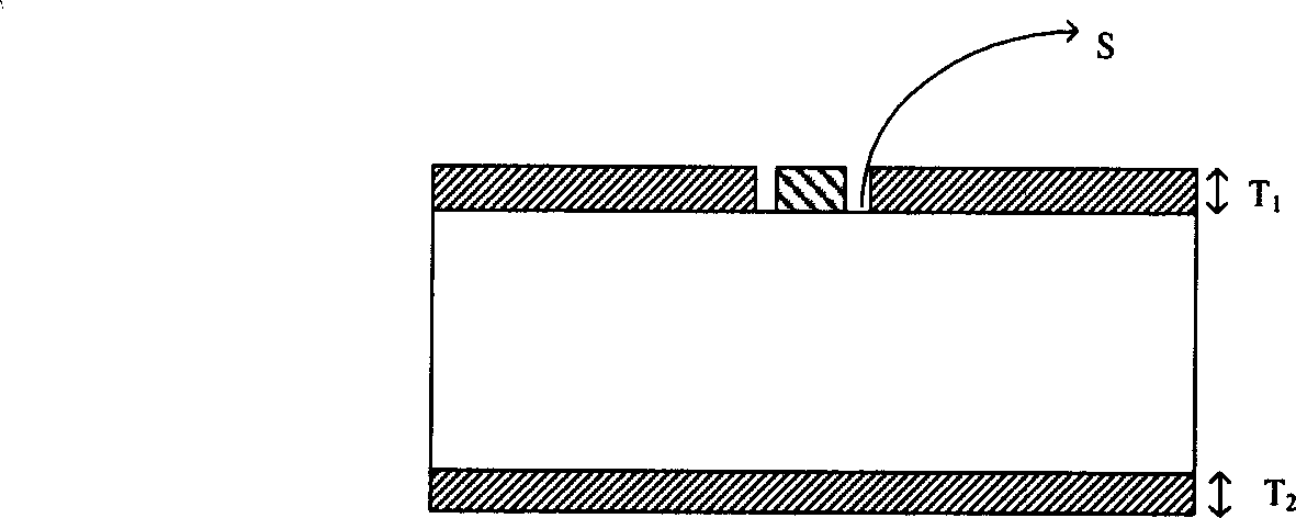
[0028] As shown in Figure 1, combining Figure 1-a The front top view of the microstrip UWB antenna and Figure 1-b The cross-sectional view of , in which the signal metal and the ground plane metal are printed on the front and back sides of the PCB board respectively, the front metal includes one signal metal and two ground plane metals, which constitute the main part of the antenna, and the signal of the antenna is from bottom to top The input or output end and the signal transmitting or receiving part, the input or output end of the signal is a coplanar waveguide with G-S-G structure to ensure the effective transmission of the signal, the antenna signal transmitting or receiving part is in the shape of a wine glass, by changing the size of the graphic and the feed point The angle can satisfy the transmission and reception of ultra-wideband pulse signals. The back of the PCB board is only paved with metal at the lower end to provide a good signal ground. This part is connect...

Embodiment 2

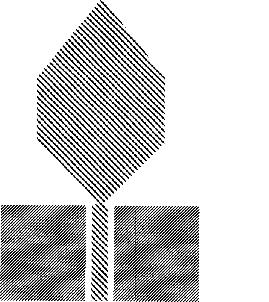
[0034] Such as figure 2 Shown is a schematic diagram of the front structure of the microstrip ultra-wideband antenna of this embodiment. The shape of the signal metal is similar to that of a wine glass, wherein the lower part of the cup body is similar to the embodiment, and the upper part is a shape composed of a triangle and a rectangle. Its key parameter θ 1 is 20°, and θ2 is 135°. There are two pieces of ground plane metal, both of which are on the front; those skilled in the art can understand that the ground plane metal in this embodiment can also be provided with another piece on the back as in embodiment 1.

Embodiment 3

[0036] Such as image 3 Shown is a schematic diagram of the front structure of the microstrip ultra-wideband antenna of this embodiment. The shape of the signal metal is similar to that of a wine glass, wherein the shape of the lower part of the cup body is similar to the above-mentioned embodiment, and the shape of the upper part is a triangle. The key parameter θ 1 is 65°, θ 2 is 50°. The ground plane gold can be set as in the first embodiment, and can also be set in the same way as in the second embodiment.


PUM


Abstract

The invention is a micro band antenna able to be applied to ultra wide band (UWB) high speed wireless communication system, comprising a printed circuit board (PCB) and a plane metal fixed on the PCB, where the plane metal comprises signal metal and ground metal, characterized in that the ground metal comprises at least two pieces, composing a í‹ground-signal-groundíŒ coplanar wave guide structure together with the signal metal, and the signal metal and ground metal can be on the same side of the PCB and also on different sides of the PCB; and the signal metal is a cup or the deformation of a cup in shape, comprising a handle and a cup body, where the lower part of the cup body is similarly an inverted triangle or trapezoid in shape. And the antenna has the characters of low cost, being easy to manufacture, small bulk and high performance.

Description

technical field [0001] The invention belongs to the application field of antennas in wireless communication, and in particular relates to the design of ultra-wideband antennas applied to 3.1-10.6GHz frequency bands. Background technique [0002] Ultra-wideband (UWB) communication technology originated in the late 1950s, and was mainly used as military technology in communication equipment such as radar. With the rapid development of contemporary wireless communication technology, people have put forward higher requirements for high-speed wireless interconnection, and the civilian use of ultra-wideband technology has been proposed again, and has attracted people's attention. UWB usually refers to a pulse signal whose absolute signal bandwidth is greater than 500MHz or the ratio of the signal bandwidth to the center frequency is greater than 25%. UWB is different from the continuous carrier used in common communication methods. It uses extremely short pulse signals to transmi...

Claims


Application Information

Patent Timeline
Patent Type & Authority Applications(China)
IPC IPC(8): H01Q13/08H01Q1/38
Inventor 杨利廖怀林邓志新黄如张兴
Owner PEKING UNIV
Why Eureka
Try Eureka