Automatic image focusing system and method

An automatic focusing and imaging technology, applied in optics, instruments, electrical and digital data processing, etc., can solve the problem of not realizing office automation, and achieve the effect of simple structure, guaranteed accuracy and low cost

Inactive Publication Date: 2006-06-21
HONG FU JIN PRECISION IND (SHENZHEN) CO LTD +1
View PDF1 Cites 22 Cited by
  • Summary
  • Abstract
  • Description
  • Claims
  • Application Information

AI Technical Summary

Problems solved by technology

[0005] However, the above-mentioned invention is only based on the adjustment of hardware devices to achieve focusing, and does not meet the requirements of office automation. Therefore, it is necessary to propose a system and method that can use a softw

Method used


Image

  • Automatic image focusing system and method
  • Automatic image focusing system and method
  • Automatic image focusing system and method

Examples


Embodiment Construction

[0016] At first, the term used in the present invention is explained as follows:

[0017] CCD: Charged Coupled Device, charge-coupled device or charge-coupled device.

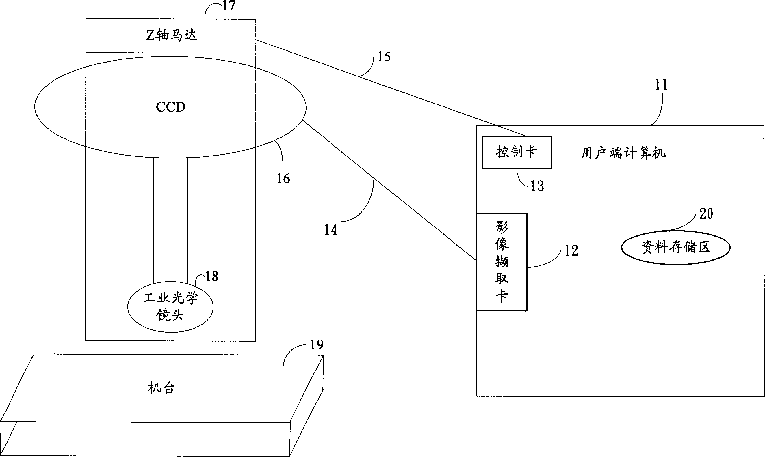
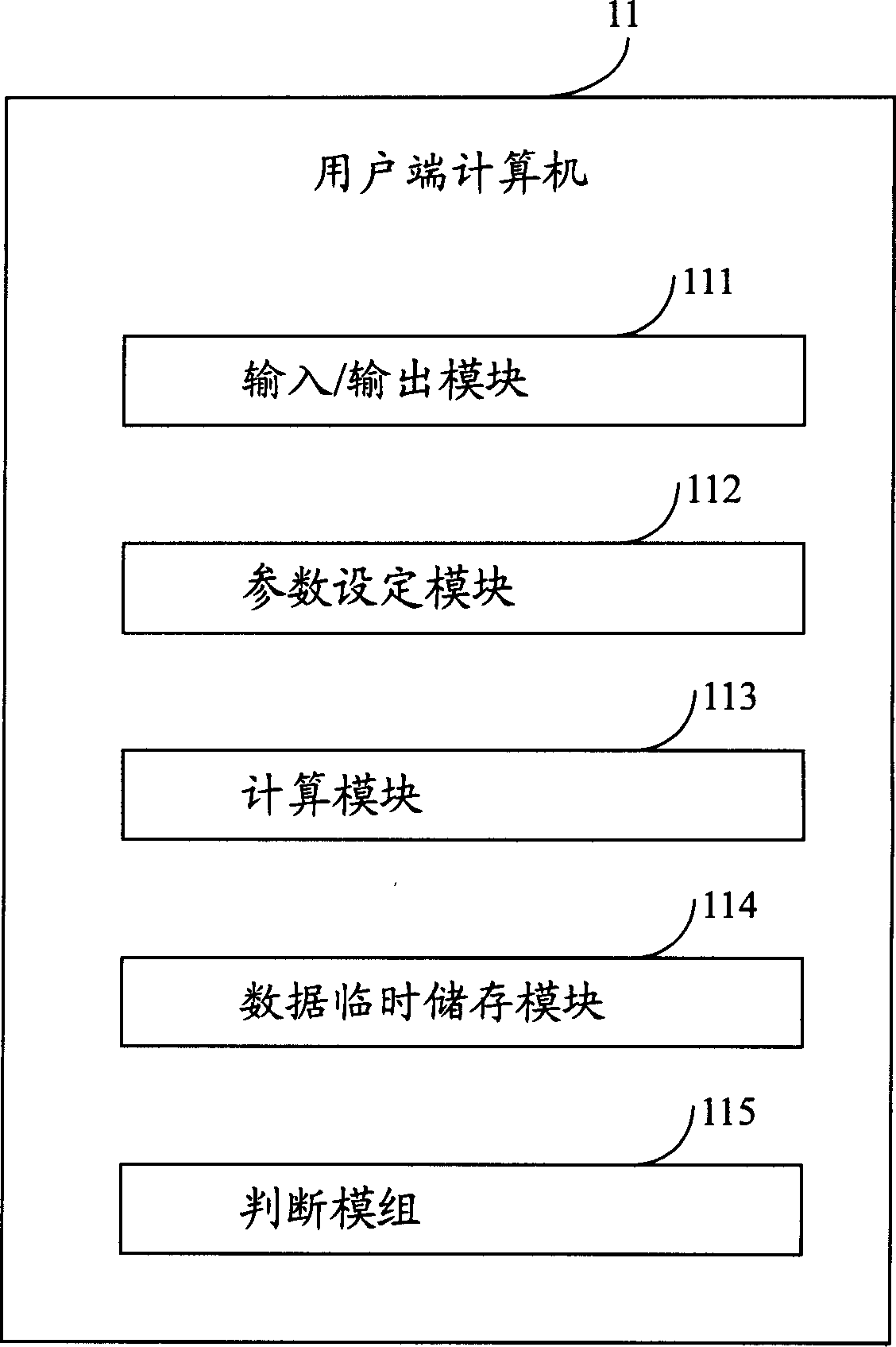
[0018] refer to figure 1 Shown is a hardware architecture diagram of the image auto-focus system of the present invention. The image auto-focus system includes a client computer 11 and a machine 19 for placing objects. Wherein, there is also a device CCD16 for collecting continuous images on the Z axis of the machine platform 19. The CCD16 is equipped with an industrial optical lens 18, and the CCD16 focuses the image through the industrial optical lens 18. The client computer 11 is equipped with an image capture card 12 , a control card 13 and a data storage area 20 . Wherein CCD16 links to each other with described image capture card 12 through an image data line 14, and CCD16 transmits the video signal obtained from machine platform to image capture card 12 through this image data line 14; Described contr...


PUM


Abstract

The invention discloses an image self-focusing method and realization system, which comprises the following steps: providing user end computer with machine measurement and focusing control function for the detected object; supplying charge coupler and industrial optical lens to gather the continual image due to measuring the Z axle of machine; providing the image acquisition card to gain the continual image; supplying the control card to send order for controlling the Z axle motor to move within the named scale; sending the focusing order to the initiating system; obtaining the image of charge coupler; predisposing the obtained image; calculating the present image articulation; judging whether the Z axle reaches in the focusing scale or second focusing; calculating the focal point according to the articulation; driving Z axle motor to reach and output the position of focal point.

Description

【Technical field】 [0001] The present invention relates to an image measurement system and method, in particular to a system and method for auto-focusing during image measurement. 【Background technique】 [0002] Office Automation (OA) is indispensable in the current information-based society. In addition to using computers to process and store large amounts of data, optical scanners (Scanners) are used as documents, forms and images. The input device is widely used because it can effectively improve the efficiency of data input processing, and has become one of the standard equipment of computers. [0003] When the existing optical scanners scan the originals of different sizes, it is achieved by switching a group of multi-lens mechanisms. When different sizes are switched to lenses with different magnifications to correspond to them, the focal length can be projected on the charge-coupled device. (Charged Coupled Device, CCD). Although these lenses adopt the same total opt...

Claims


Application Information

Patent Timeline
IPC IPC(8): G02B27/16G02B7/28G06F3/00
Inventor 蒋理张旨光
Owner HONG FU JIN PRECISION IND (SHENZHEN) CO LTD
Why Eureka
Try Eureka