
Method for cleaning sic particles

A technology of silicon carbide particles and particles, applied in chemical instruments and methods, fine working devices, separating solids from solids with airflow, etc., can solve problems such as no economic feasibility

Inactive Publication Date: 2006-06-21
METAL MFGS LTD
View PDF0 Cites 7 Cited by
  • Summary
  • Abstract
  • Description
  • Claims
  • Application Information

AI Technical Summary

Problems solved by technology

Separation according to this principle is not economically feasible in the industrial production of silicon wafers

Method used


Image

  • Method for cleaning sic particles
  • Method for cleaning sic particles
  • Method for cleaning sic particles

Examples


Embodiment 1

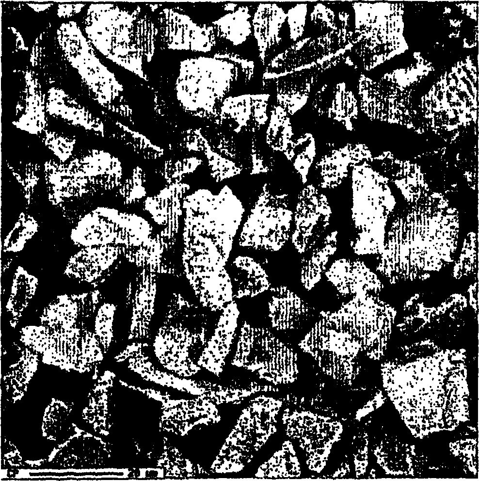
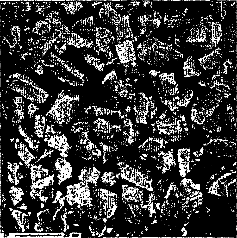
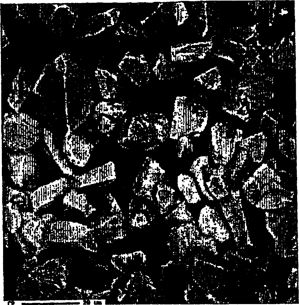
[0068] SiC particles were processed as described above and are shown in Figure 4 middle.

[0069] First, the material was classified in an Alpine air classifier model 50ATP at 4500 rpm or 235 rad / sec. This requires the removal of coarse particles. Particles (agglomerates) larger than 27 μm were processed in a jet mill of type AFG100, in which the agglomerates were broken up, with 98% of the yield obtained being in the fraction smaller than 27 μm.

[0070] The fine particle fraction from step (a) is thereafter classified in the aforementioned Alpine unit at a speed of 10,000 rpm or 520 radians / second in order to remove particles smaller than about 3 μm, which is smaller than the desired size in the product. In this step, 96.5% by weight of the output was obtained as pre-fractionated product, calculated from the weight of the fine particle fraction leaving step (a).

[0071] Therefore, the total yield is 94.5%. 5 to 8 show the results of Example 1.

Embodiment 2

[0073] Example 2 was carried out to show that the method of the invention can be used on an industrial scale. Industrial scale tests were carried out in an air classifier of type SAC200 (Sintef Air Classifier 200) to demonstrate that the silicon carbide priory used for cutting silicon wafers meets FEPA F500 standards. The air classifier SAC200 has a production capacity of up to 800 kg / h. The test procedure was equivalent to Example 1 except that the jet mill was omitted.

[0074] In the first step of classification, a rotation speed of 850 rpm corresponding to 45 rad / s was used.

[0075] In both the first and second steps, 350 kg of polluting material was fed to the classifier per hour.

[0076] At this speed, coarse particles / agglomerates are separated from finer material. Angular velocity and local gas velocity provide the maximum particle size corresponding to FEPA standard F500.

[0077] In step two, the rotation speed was increased to 5500 rpm corresponding to 290 rad...


PUM


Abstract

Method for cleaning of silicon carbide particles from fine grain particles adhering to said silicon carbide particles, typically in the form of agglomerates of metal particles, subsequent to production (cutting) of silicon wafers and after removal of any present solute or dispersing agent from the particles. The particles (1) of contaminated silicon carbide are firstly exposed to a mechanical treatment in a first step (2) of cleaning in a per se known classifying apparatus where a first coarse fraction (3) of particles, agglomerates, larger than the original silicon carbide particles, are separated out and treated in a process (4) where the agglomerates are broken down to individual grains, without crushing said individual grains, and thereafter recycled (5) to said first step (2) of cleaning. A first fine fraction (6) is discharged from said first step (2) and transferred to a second step (7) of cleaning conducted in a per se known classifying apparatus from which the particles of silicon carbide are discharged in the form of a second coarse fraction (8), while the contaminants separated out in said second step of cleaning, are discharged in the form of a second fine fraction (9).

Description

[0001] The present invention relates to a method of cleaning SiC (silicon carbide) particles. More particularly, the present invention relates to a method for cleaning spent SiC particles from a suspension of cutting media used in cutting or sawing silicon wafers for use in solar cells and electronic devices, commonly referred to as waste cutting slurry . Background technique [0002] When sawing thin silicon wafers, commonly referred to as "wafers", silicon carbide particles belonging to FEPA grades F400, F500 and F600 are dispersed in an organic liquid to form a suspension that acts as a cutting medium. The most common dispersants are organic glycol liquids such as polyethylene glycol or dipropylene glycol with added surface tension-reducing surfactants. [0003] Sawing, usually performed by a wire saw with a thin, hardened steel wire with a brass surface, cuts the block of silicon into a series of thin wafers, while the particles dislodged from the sawing are suspended in ...

Claims


Application Information

Patent Timeline
IPC IPC(8): B28D1/02B07B9/02B24B55/12B24B57/00B28D5/00
CPCB07B9/02B24B55/12B24B57/02B28D5/007Y02P70/10
Inventor O·S·拉尼斯J·赫梅拉尔
Owner METAL MFGS LTD
Learn More