Switching frequency period modulated sawteeth wave generating circuit

A technology of periodic modulation and generating circuits, applied in the direction of pulse generation, electrical components, pulse technology, etc., can solve the problems of high interference level, low reliability, low interference level, etc., achieve strong versatility, low additional cost, and realize easy effect

Inactive Publication Date: 2006-06-28
SHANGHAI JIAO TONG UNIV
View PDF0 Cites 12 Cited by
  • Summary
  • Abstract
  • Description
  • Claims
  • Application Information

AI Technical Summary

Problems solved by technology

The traditional PWM chopping technology adopts a fixed switching frequency modulation scheme. In its high-frequency harmonic distribution law, the interference level of the integer multiple of the switching frequency and its side frequency is quite high, and the interference level of other areas is relatively low, which belongs to narrow-band distribution. Certain spectral regions have difficulty passing quasi-peak and average EMI standard limits
For this reason, some new switching frequency modulation techniques have emerged, such as random modulation of switching frequency, random modulation of pulse position, and switching frequency jitter technology. The technology has not yet been popularized and applied in the field of power electronic converters, so it is necessary to find a switching frequency modulation technology that is simple and easy to implement and has a good EMI suppression effect

Method used


Image

  • Switching frequency period modulated sawteeth wave generating circuit
  • Switching frequency period modulated sawteeth wave generating circuit

Examples


Embodiment Construction

[0011] The technical solutions of the present invention will be further described below in conjunction with the accompanying drawings and embodiments. The following examples are further illustrations of the present invention, but do not constitute a limitation of the present invention.

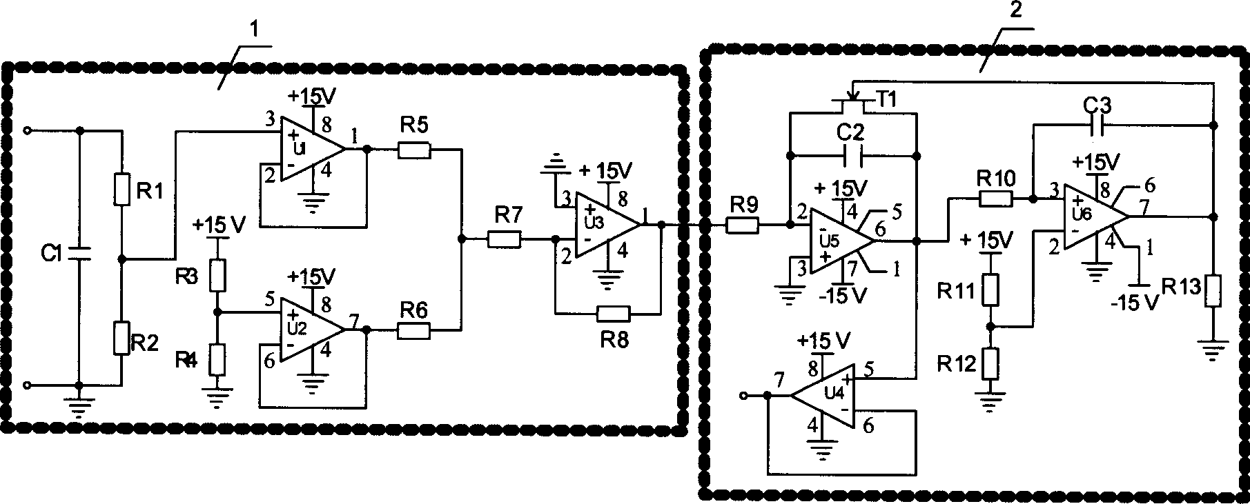
[0012] The sawtooth wave generation circuit of the switching frequency periodic modulation of the present invention design is as figure 1 As shown, it is composed of modulation wave circuit 1 and sawtooth wave circuit 2. Modulating wave circuit 1 is composed of three operational amplifiers U1, U2 and U3, one capacitor C1, and eight resistors R1-R8. The capacitors and resistors are respectively connected to each pin of the operational amplifier. The sawtooth wave circuit 2 is composed of two operational amplifiers U4 and U5, a voltage comparator U6, two capacitors C2 and C3, a junction field effect transistor T1, and five resistors R9~R13. The capacitors and resistors are respectively connecte...


PUM


Abstract

This invention relates to a saw-tooth wave generation circuit for modulating switch frequency period composed of a modulation circuit and a saw tooth wave circuit, in which, the input of the modulation wave circuit is sine half-wave voltage and gets modulation wave voltage after the level is upgraded by a branch voltage circuit, a follow circuit and a DC bias component, the saw-tooth wave circuit inputs said modulation wave voltage to generate saw-tooth wave voltage signal via a charge and discharge circuit with the period modulated and a comparison circuit to be output by the voltage comparator, which generates saw-tooth wave voltage signal with the switch frequency varied along with the sine half-wave voltage period as the carrier signals to greatly reduce the magnetic interference intensity based on the theory of voltage-frequency conversion.

Description

technical field [0001] The invention relates to a sawtooth wave generation circuit with periodic modulation of switching frequency, in particular to an active power electronic conversion circuit suitable for active power factor correction (PFC), active power filter (APF) and switching power supply (SMPS). The switching frequency of the device is modulated according to the law of the half-sine wave sawtooth wave generating circuit, which has a very wide range of applications. Background technique [0002] Since power electronic conversion technology generally adopts high-frequency PWM (pulse width modulation) chopping technology, high-intensity electromagnetic interference (EMI) will be generated, and power electronic conversion products must pass relevant EMI tests before they go on the market, such as continuous disturbance radiation, For test items such as power radiation, EMI design has already accounted for an important part of the initial product design cost, so suppres...

Claims


Application Information

Patent Timeline
Patent Type & Authority Applications(China)
IPC IPC(8): H03K4/08H03K4/48
Inventor 杨喜军
Owner SHANGHAI JIAO TONG UNIV
Why Eureka
Try Eureka