Tri-switch single-stage voltage boosting/reducing inverter
An inverter and three-switch technology, which is applied in the field of single-stage buck-boost inverters, can solve the problem of high switching loss and switching stress of switching tubes, complex circuit structure of single-stage inverters, and poor voltage amplitude adjustment. Flexibility and other issues to achieve the effect of compact structure, easy control and implementation, high-quality output current or voltage
- Summary
- Abstract
- Description
- Claims
- Application Information
AI Technical Summary
Problems solved by technology
Method used
Image
Examples
specific Embodiment approach 1
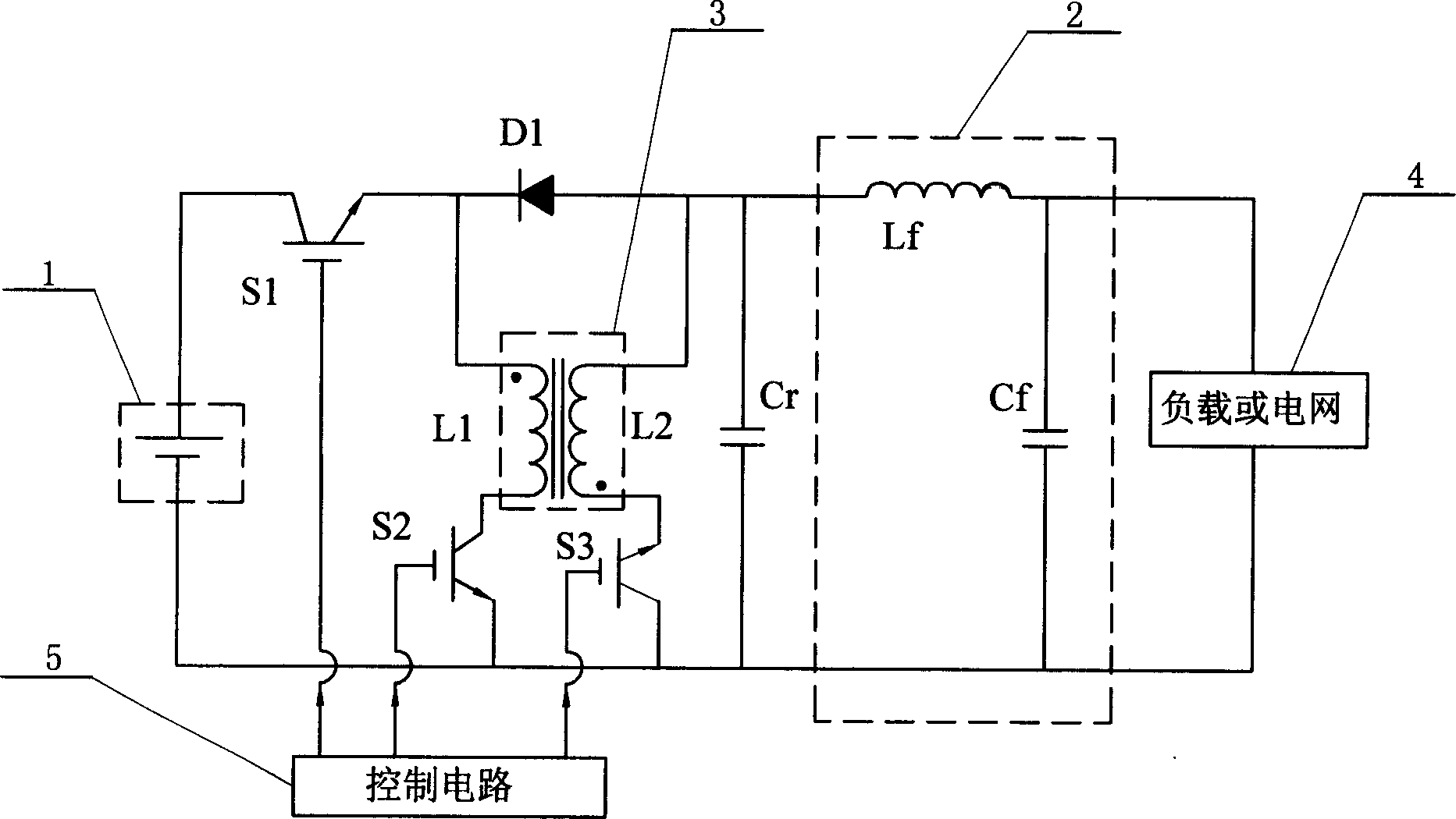
[0008] Specific implementation mode one: see figure 1 , the inverter in this specific embodiment consists of a high-pass filter 2, a control circuit 5, a main self-shutoff switch S1, a first auxiliary self-shutoff switch S2, a second auxiliary self-shutoff switch S3, a high-frequency inverter Composed of excitation transformer 3, resonant capacitor Cr and power diode D1, the positive output terminal of DC power supply 1 is connected to the collector of the main self-shutdown switch S1, and the emitter of the main self-shutoff switch S1 is connected to the high-frequency flyback transformer 3 The same-named end of the primary coil L1 and the negative end of the power diode D1, the positive end of the power diode D1 are connected to the non-identical end of the secondary coil L2 of the high-frequency flyback transformer 3 and one end of the resonant capacitor Cr, and the high-frequency flyback transformer 3 The terminal with the same name of the secondary coil L2 is connected to...
specific Embodiment approach 2
[0009] Specific implementation mode two: see figure 1 The difference between this embodiment and Embodiment 1 is that the high-pass filter 2 includes a filter inductor Lf, one end of the resonant capacitor Cr is connected to one end of the filter inductor Lf, and the other end of the filter inductor Lf is connected to the load or the grid 4 One input end of the resonant capacitor Cr is connected to the other input end of the load or grid 4 . Other composition and connection relationship with
[0010] The specific embodiment one is the same.
specific Embodiment approach 3
[0011] Specific implementation mode three: see figure 1 The difference between this specific embodiment and the second specific embodiment is that: the high-pass filter 2 also includes a filter capacitor Cf, and the filter capacitor Cf is connected in parallel between the two input terminals of the load or the grid 4 . Other compositions and connections are the same as those in the second embodiment. Embodiment 3 Compared with Embodiment 2, the filter capacitor Cf is omitted, which will reduce the burden of the filter inductor Lf.
PUM
 Abstract
Description
Claims
Application Information
 - R&D
- Intellectual Property
- Life Sciences
- Materials
- Tech Scout
- Unparalleled Data Quality
- Higher Quality Content
- 60% Fewer Hallucinations
Browse by: Latest US Patents, China's latest patents, Technical Efficacy Thesaurus, Application Domain, Technology Topic, Popular Technical Reports.
© 2025 PatSnap. All rights reserved.Legal|Privacy policy|Modern Slavery Act Transparency Statement|Sitemap|About US| Contact US: help@patsnap.com


