

Sensitive dye solar battery with nanometer crystal TiO2
A technology of solar cells and nanocrystals, applied in the field of solar cells, can solve the problems of low photoelectric conversion efficiency of solar cells, low ion migration rate, etc., achieve long working life and avoid failure effects
- Summary
- Abstract
- Description
- Claims
- Application Information
AI Technical Summary
Problems solved by technology
Method used
Image

Examples
Embodiment 1
[0043] The base material used in preparing the semiconductor electrode 1 is ITO conductive glass with a surface resistance of 20-30 ohms, which is cut into a size of 2.5cm×2.5cm, and then cleaned. The nanocrystalline TiO used 2 The powder is P25 type TiO for industrial use 2 Powder with an average particle size of 25-30nm and a specific surface area of 50m 2 / g,TiO 2 The content is greater than 99.5%, and it is a mixed structure of anatase phase and rutile phase. Preparation of TiO on ITO Conductive Glass by Powder Coating Method 2 The film, the process is: mix 8mL deionized water and 1.0g P25 powder fully, add a few drops of PEG and fully grind it to prepare a suspension slurry, apply the prepared slurry evenly on the cut and On the cleaned ITO conductive glass, keep it warm at 450°C for 60 minutes. Then will have been coated with TiO 2 The thin film of ITO conductive glass is dipped into the dye solution. The dye used is N3 dye, and the dye solution is prepared by u...
Embodiment 2
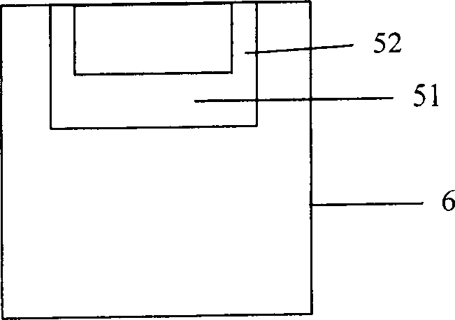
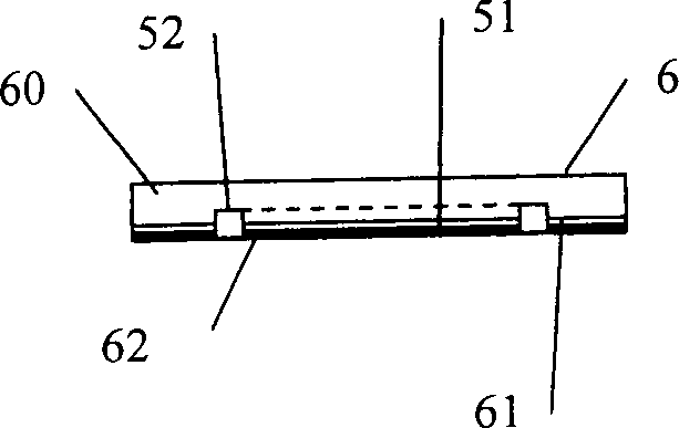
[0049] The semiconductor electrode 1, the liquid electrolyte 5, and the sealing method of this embodiment are all the same as those of the embodiment 1. The difference from Embodiment 1 is that in this embodiment, the side of the counter electrode 6 facing away from the semiconductor electrode 1 is corroded with hydrofluoric acid to form a liquid storage pool 51 and a liquid replacement channel 52, and at the same time, on the counter electrode 6 forming through-holes 63, such as Figure 7 , 8 shown. In addition, in this embodiment, a cover plate 64 is provided. The cover plate 64 is a piece of flat glass, used to cover the liquid reservoir 51 and the liquid replenishment channel 52 on the counter electrode 6 . Illustration of the cover plate 64 is omitted here. The resulting TiO 2 The structure of the solar cell is as Figure 9 shown.
[0050] Figure 10 Represents the TiO of Example 2 2 The relationship between the short-circuit current of a solar cell and time. Fr...
Embodiment 3
[0052] The semiconductor electrode 1, the liquid electrolyte 5, and the sealing method of this embodiment are all the same as those of the second embodiment.
[0053] Different from Embodiment 2, in this embodiment, a through hole 63 is opened on the counter electrode 6, such as Figure 11 , 12 shown. On the side of the cover plate 64 facing the counter electrode 6, a liquid reservoir 51 and a liquid replenishment channel 52 are arranged, such as Figure 13 , 14 shown. The resulting TiO 2 The structure of the solar cell is as Figure 15 shown.
[0054] Figure 16 Represents the TiO of Example 3 2 The relationship between the short-circuit current of a solar cell and time. From Figure 16 Known, the TiO of embodiment 3 2 The function of the solar cell is almost the same as that of Embodiment 2. TiO of Example 3 2 The variation of the open-circuit voltage of the solar cell is the same as that of Example 2, and description thereof is omitted here.
[0055] Since the...
PUM
| Property | Measurement | Unit |
|---|---|---|
| electrical resistance | aaaaa | aaaaa |
| particle size | aaaaa | aaaaa |
| specific surface area | aaaaa | aaaaa |
Abstract
Description
Claims
Application Information