Check patentability & draft patents in minutes with Patsnap Eureka AI!

Radio communication system

An antenna and signal technology, applied in the field of radio communication systems, can solve the problems of inability to reduce costs, difficult to miniaturize base stations and control stations, and increase in scale, and achieve the effects of miniaturization, reduction in number, and simplification of structure.

Inactive Publication Date: 2006-08-16
KK TOSHIBA
View PDF0 Cites 4 Cited by
  • Summary
  • Abstract
  • Description
  • Claims
  • Application Information

AI Technical Summary

Problems solved by technology

[0011] On the other hand, if the optical fibers are provided from the individual antenna parts, the number of optical fibers for connecting the base station and the control station is greatly increased, and accordingly the construction of optical transmitters such as optical / electrical converters and electrical / optical converters becomes complicated, bigger
[0012] Therefore, in a conventional radio communication system equipped with an adaptive antenna and using ROF technology for signal transmission, since the optical transmitter requires many constituent elements, the system configuration is complicated, it is difficult to miniaturize the base station and the control station, and the cost cannot be reduced

Method used


Image

  • Radio communication system
  • Radio communication system
  • Radio communication system

Examples


no. 1 example

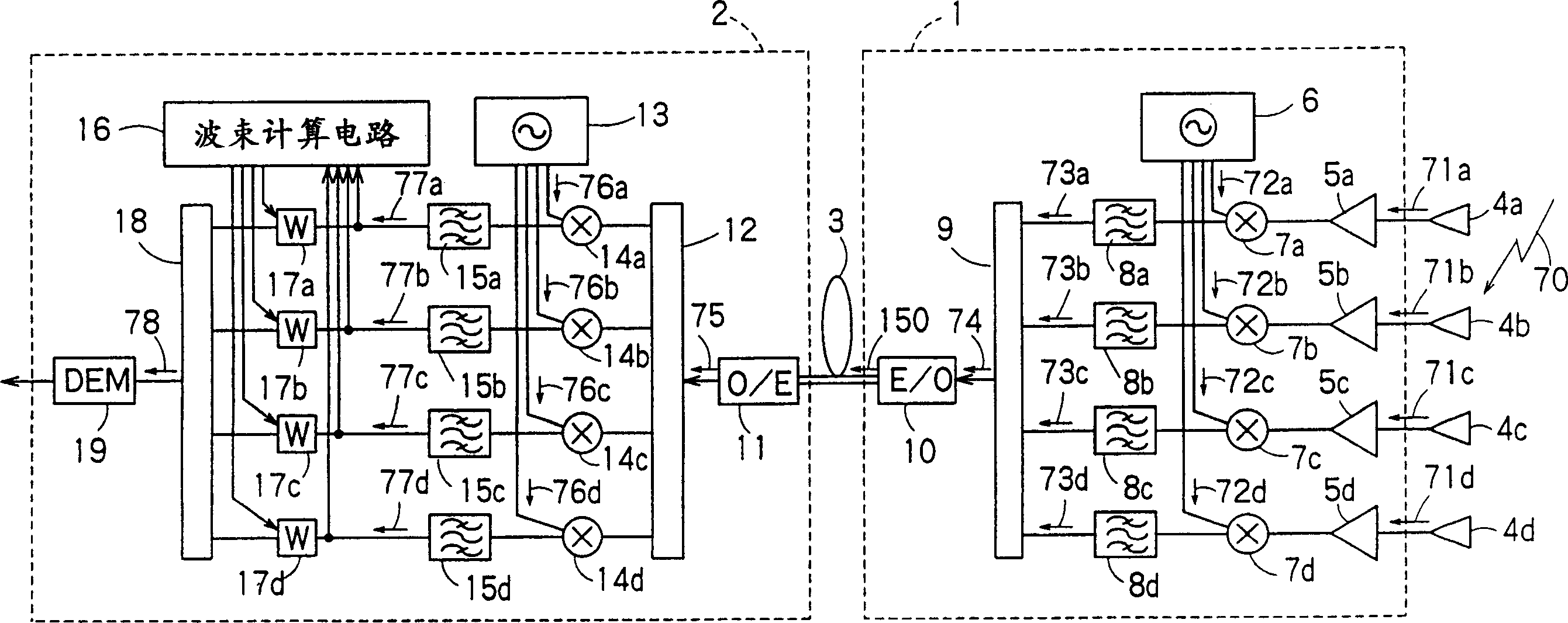
[0119] image 3 is a block diagram schematically illustrating the construction of the first embodiment of the radio communication system according to the present invention. image 3 The radio communication system of is constituted by a base station 1 and a control station 2, and the two stations are connected to each other by an optical fiber 3.

[0120] The base station 1 has array antennas 4a to 4d composed of four antenna parts, low noise amplifiers 5a to 5d, a base station local oscillator (first local oscillator) 6, multipliers (base station side frequency conversion means) 7a to 7d, band Pass filters 8a to 8d, coupler (subcarrier multiplexed signal generation means) 9, and electrical / optical converter (E / O converter: base station side transmission means) 10.

[0121] The control station 2 has an optical / electrical converter (O / E converter) 11, a distributor 12, a control station local oscillator (second local oscillator) 13, multipliers (control station side frequency c...

no. 2 example

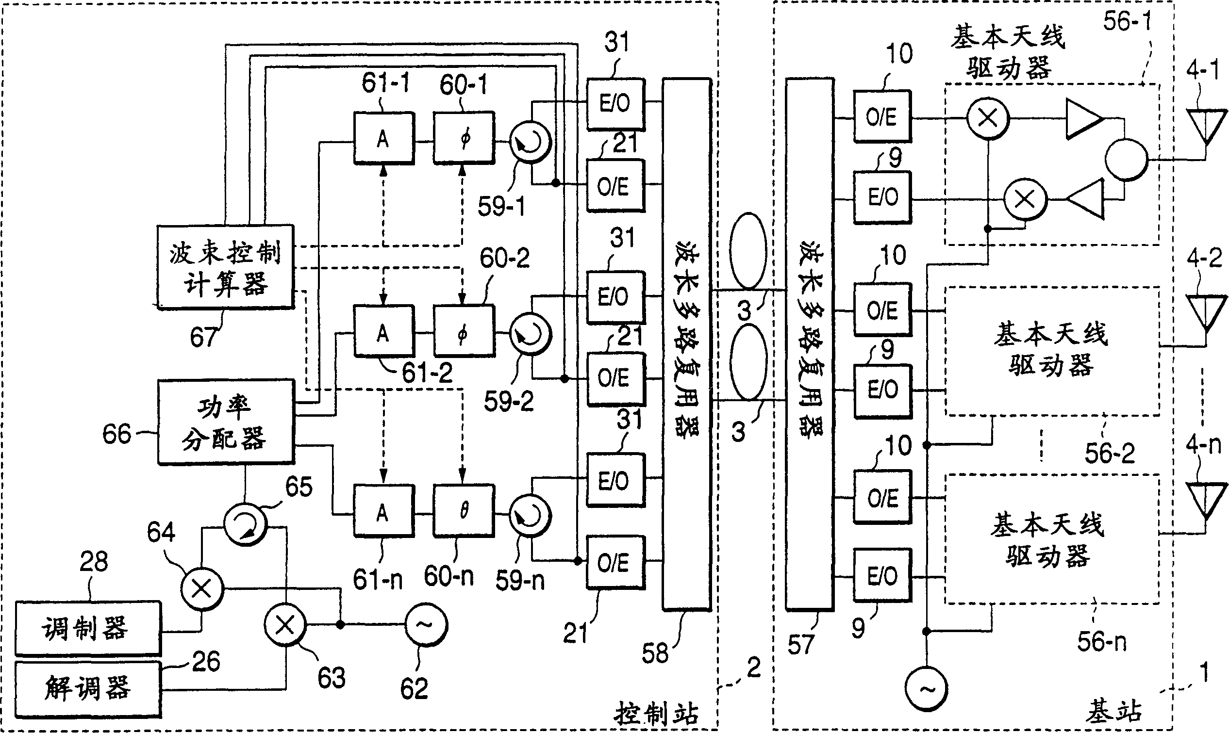
[0201] In the second embodiment, the reference signal output from the base station local oscillator 6 and the reference signal output from the control station local oscillator 13 are shared.

[0202] Figure 8 is a block diagram of the second embodiment of the radio communication system according to the present invention. exist Figure 8 in, with image 3 The same constituent parts are denoted by the same reference numerals, and the following descriptions are mainly different from image 3 aspect.

[0203] exist Figure 8 In the radio communication system of , the configuration of the receiver from the base station 1 to the control station 2 is similar to that of the first embodiment, except for the configuration of the base station local oscillator 6 and the control station local oscillator 13 .

[0204] Figure 8 The radio communication system is characterized in that the configuration of the transmitter from the control station 2 to the base station 1 is newly added, ...


PUM


Abstract

PROBLEM TO BE SOLVED: To realize a small-size inexpensive wireless communication system by considerably simplifying the configuration of a radio base station side. SOLUTION: In the wireless communication system where a radio base station with a variable directivity array antenna and a control station communicate with each other by means of an ROF, a signal of each element of the array antenna is frequency-converted into a plurality of signals with different frequencies, a reference signal whose frequency is apart from those of a plurality of the signals by a prescribed frequency is multiplexed on a plurality of the signals and the multiplexed signal is transmitted through the same optical fiber 112. According to this method, the number of electrooptic converters and photoelectric converters can be reduced and the configuration of the radio base station can considerably be simplified, then the inexpensive and small-sized wireless communication system can be built up. Moreover, since all the signals are transmitted by using the single optical fiber 112, relative phase fluctuation due to expansion / contraction of each optical fiber on the way of transmission can be avoided in this configuration.

Description

[0001] This application is a divisional application of the Chinese patent application number 00137024.3, the filing date is September 13, 2000, and the invention title is "radio communication system". Technical field: [0002] The present invention relates to a radio communication system consisting of a base station equipped with a variable beam pattern array antenna such as an adaptive array antenna, and a control station connected to the base station through an optical fiber. Controls the function of the variable beam pattern array antenna. Background technique: [0003] Radio-over-fiber (ROF) technology represented by mobile phones and intelligent transmission systems (TTS) has received widespread attention. In order to realize signal transmission, this technology uses optical fibers to connect base stations and control stations to communicate with moving objects. According to the ROF technology, radio signals are transmitted from the base station to the control station v...

Claims


Application Information

Patent Timeline
IPC IPC(8): H04B7/08H01Q3/26H04J14/02H04B1/50H04B10/00H04B10/25H04J14/00H04W16/28H04W92/12
Inventor 濑户一郎村上康柴田治松冈秀浩
Owner KK TOSHIBA
Features
  • R&D
  • Intellectual Property
  • Life Sciences
  • Materials
  • Tech Scout
  • Unparalleled Data Quality
  • Higher Quality Content
  • 60% Fewer Hallucinations
Learn More