
Method for realizing frequency monitoring by high-frequency radar receiver

A receiver and spectrum monitoring technology, applied in transmission monitoring, electrical components, transmission systems, etc., can solve problems such as increasing R&D costs and system complexity, and no spectrum monitoring function, saving development costs, reducing system complexity, The effect of broad application prospects

Inactive Publication Date: 2006-08-16
WUHAN UNIV
View PDF1 Cites 20 Cited by
  • Summary
  • Abstract
  • Description
  • Claims
  • Application Information

AI Technical Summary

Problems solved by technology

The existing spectrum monitoring scheme adopts equipment based on noise spectrum analysis and radar equipment works on the principle of time-sharing. Spectrum monitoring is designed as an independent module, which does not occupy the resources of the radar host, but increases the research and development Cost and System Complexity
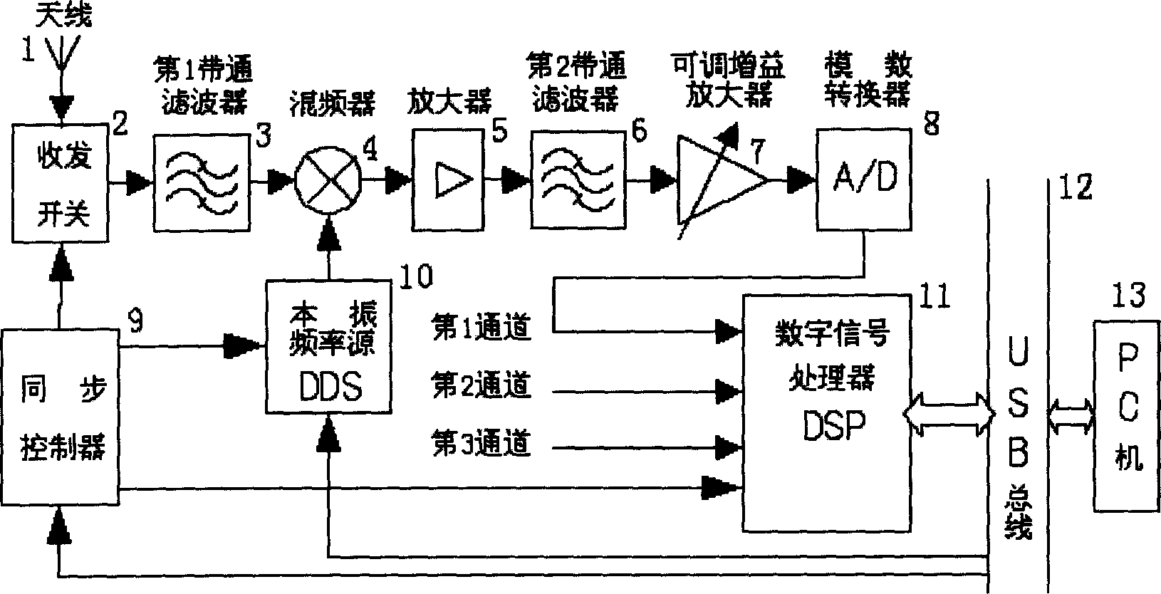
[0004] A utility model patent of Wuhan University "High Frequency Ground Wave Radar Digital Coherent Receiver" (ZL: 200420057632.3), such as figure 1 , consisting of an antenna 1, a transceiver switch 2, a first bandpass filter 3, a mixer 4, an amplifier 5, a second bandpass filter 6, an adjustable gain amplifier 7, an analog-to-digital converter 8, a synchronous controller 9, Composed of local oscillator frequency source 10, digital signal processor 11, USB bus 12, and PC 13; use transceiver co-station, linear frequency modulation interrupt continuous wave, primary mixing band-pass sampling and digital signal processor to complete multi-channel data processing; Stable performance, simple structure, good system linearity and dynamic stability; but no spectrum monitoring function

Method used


Image

  • Method for realizing frequency monitoring by high-frequency radar receiver
  • Method for realizing frequency monitoring by high-frequency radar receiver
  • Method for realizing frequency monitoring by high-frequency radar receiver

Examples


Embodiment Construction

[0031] Below in conjunction with accompanying drawing and embodiment describe in detail:

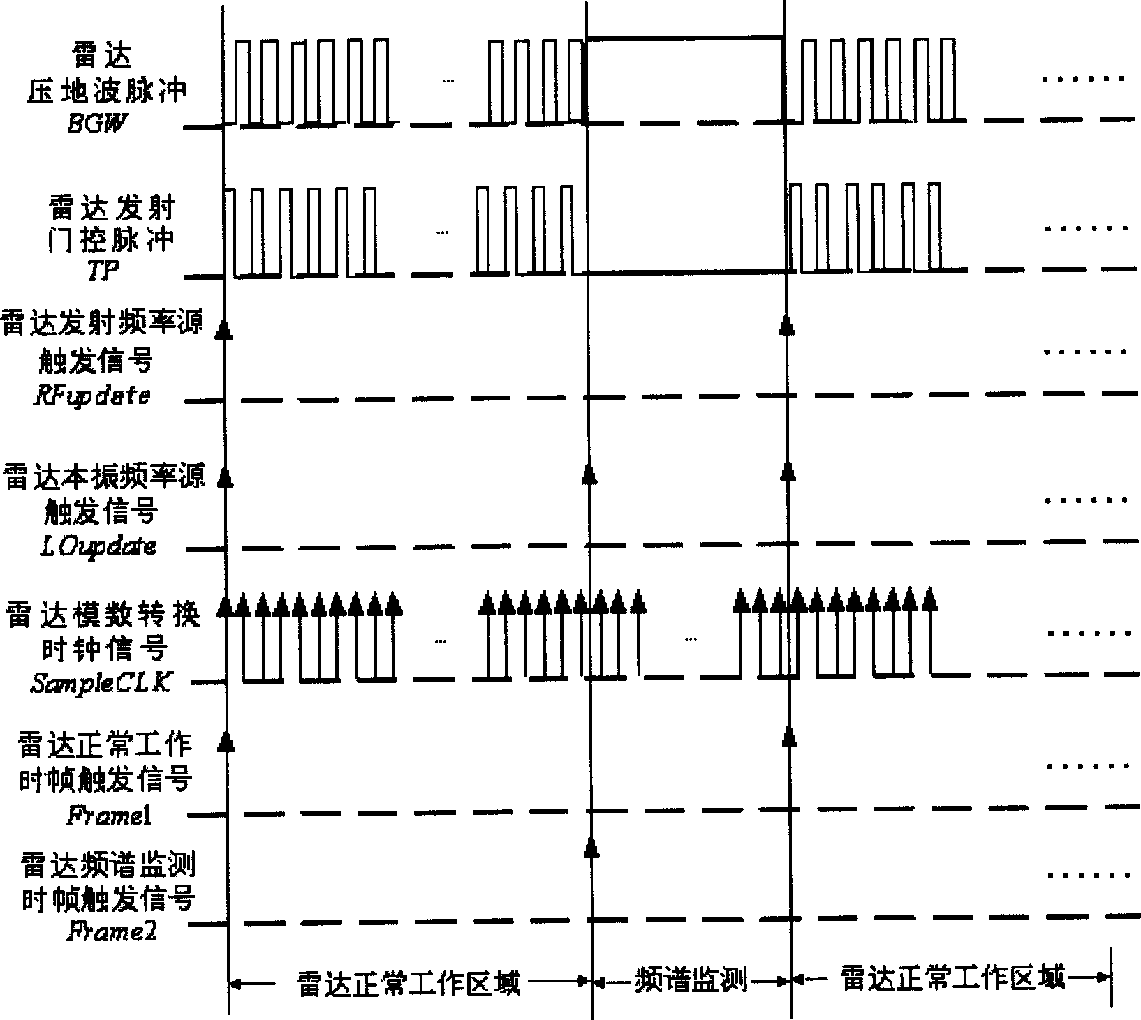
[0032] The present invention monitors the external noise environment by utilizing the intermittent period of the normal operation of the radar, and obtains the statistics of the external noise in a relatively wide frequency range after N cycles, and selects the optimal operating frequency to carry out the operation parameters of the radar frequency source. Update, so as to achieve real-time anti-jamming performance, and at the same time without adding an additional spectrum monitoring module.

[0033] 1, working principle of the present invention

[0034] (1) Linear Frequency Modulation Interrupted Continuous Wave (FMICW) Waveform Analysis

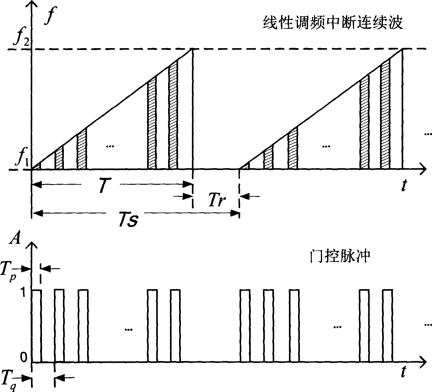
[0035] FMICW is a pulse compression system widely used in modern radars, which can obtain satisfactory velocity resolution and distance resolution, and uses pulse gating modulation to achieve effective isolation between transmission and reception, p...


PUM


Abstract

The method is used for implementing a real time spectrum monitoring on the basis of current higher-frequency radar. The work gap of higher-frequency radar is used to monitor the external interference noise spectrum, and to implement the realtime statistic for external noise environment. According to the result of statistic the working frequency of radar is renewed. The invention can also implement the reception of radar back wave and environment monitoring in outer space.

Description

technical field [0001] The invention relates to a high-frequency radar receiving technology; specifically, it is a method with real-time spectrum monitoring function completed on the basis of the existing high-frequency radar receiver. Background technique [0002] The high-frequency surface wave radar marine environment monitoring system is an advanced radar system developed by Wuhan University to detect marine environmental elements such as wind, waves, current fields and low-speed moving targets on the ocean surface. The system uses linear frequency modulation pulse compression and software radio technology, and the receiver adopts multi-channel receiving technology and array signal processing technology to obtain rich ocean state information. [0003] Due to the existence of environmental noise and external interference, the performance of radar detection is directly affected. In order to select a high-quality radar operating frequency, it is very important to monitor a...

Claims


Application Information

Patent Timeline
IPC IPC(8): H04B17/00
Inventor 文必洋沈伟周浩白立云杨静
Owner WUHAN UNIV
Learn More