Power switching circuit

A power switch and circuit technology, applied in battery circuit devices, circuit devices, emergency protection circuit devices, etc., can solve problems such as poor usability, limited scope of application, and difficulty in applying to portable devices

Inactive Publication Date: 2006-10-04
RICOH KK
View PDF2 Cites 15 Cited by
  • Summary
  • Abstract
  • Description
  • Claims
  • Application Information

AI Technical Summary

Problems solved by technology

[0011] However, in the above-mentioned prior art, the scope of application is limited, the usability is poor, and improvement is required in effectively preventing inrush current
[0012] That is, in the prior art described in Patent Document 1 and Patent Document 3, since the resistor is connected in series to the power supply, it can be connected to the secondary side of the power supply, but on the primary side connected to the battery, the non-operating current is large, making it difficult to apply For portable devices, the scope of application is limited and the usability is poor
[0013] In addition, in the prior art described in Patent Document 2, the problems of Patent Document 1 and Patent Document 3 are improved by connecting a resistor to the MOSFET, but a bias current circuit is required, and a circuit for driving the bias current circuit is required. driving voltage
In addition, the bias current circuit is difficult to drive at a low input voltage of about two AA alkaline batteries, or due to the bias current circuit itself, not only an additional power supply that becomes a large load is required, but also the power supply There is no countermeasure for the inrush current at startup itself, so there is a problem that a large inrush current occurs at startup

Method used


Image

  • Power switching circuit
  • Power switching circuit
  • Power switching circuit

Examples


Embodiment 1

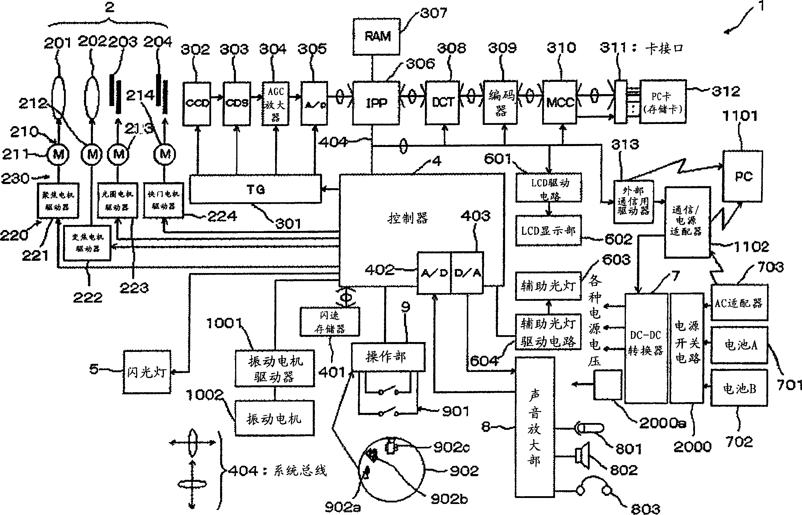
[0038] figure 1 as well as figure 2 It is a figure showing the first embodiment of the power switch circuit of the present invention, figure 1 It is a block diagram of main parts of the digital camera 1 to which the first embodiment of the power switch circuit of the present invention is applied.

[0039] exist figure 1 Among them, the digital camera 1 includes: a lens system 2 including a focus lens system 201, a zoom lens system 202, an aperture 203, a shutter 204, etc., a motor system 210, a drive system 220, a TG (Timing Generator, timing generator) section 301, a CCD (Charge coupled device) 302, CDS (correlated double sampling) circuit 303, variable gain amplifier (AGC amplifier) ​​304, A / D converter 305, IPP (Image Pre-Processor, image preprocessor) 306, RAM (internal memory) 307, DCT (Discrete Cosine Transform, discrete cosine transform) 308, encoder (Huffman encoder / decoder) 309, MCC (Memory Card Controller, memory card controller) 310, card interface 311, PC card ...

Embodiment 2

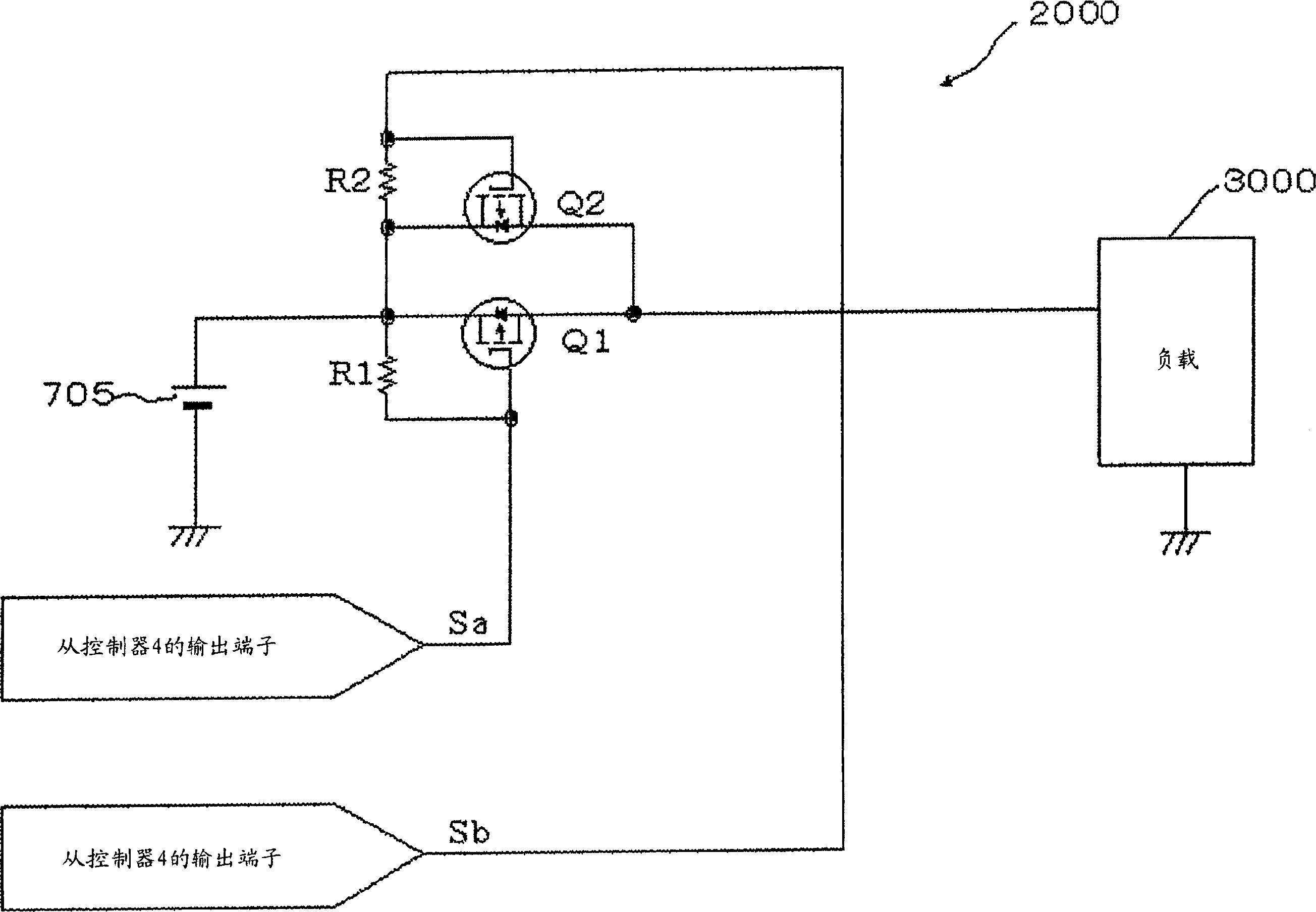
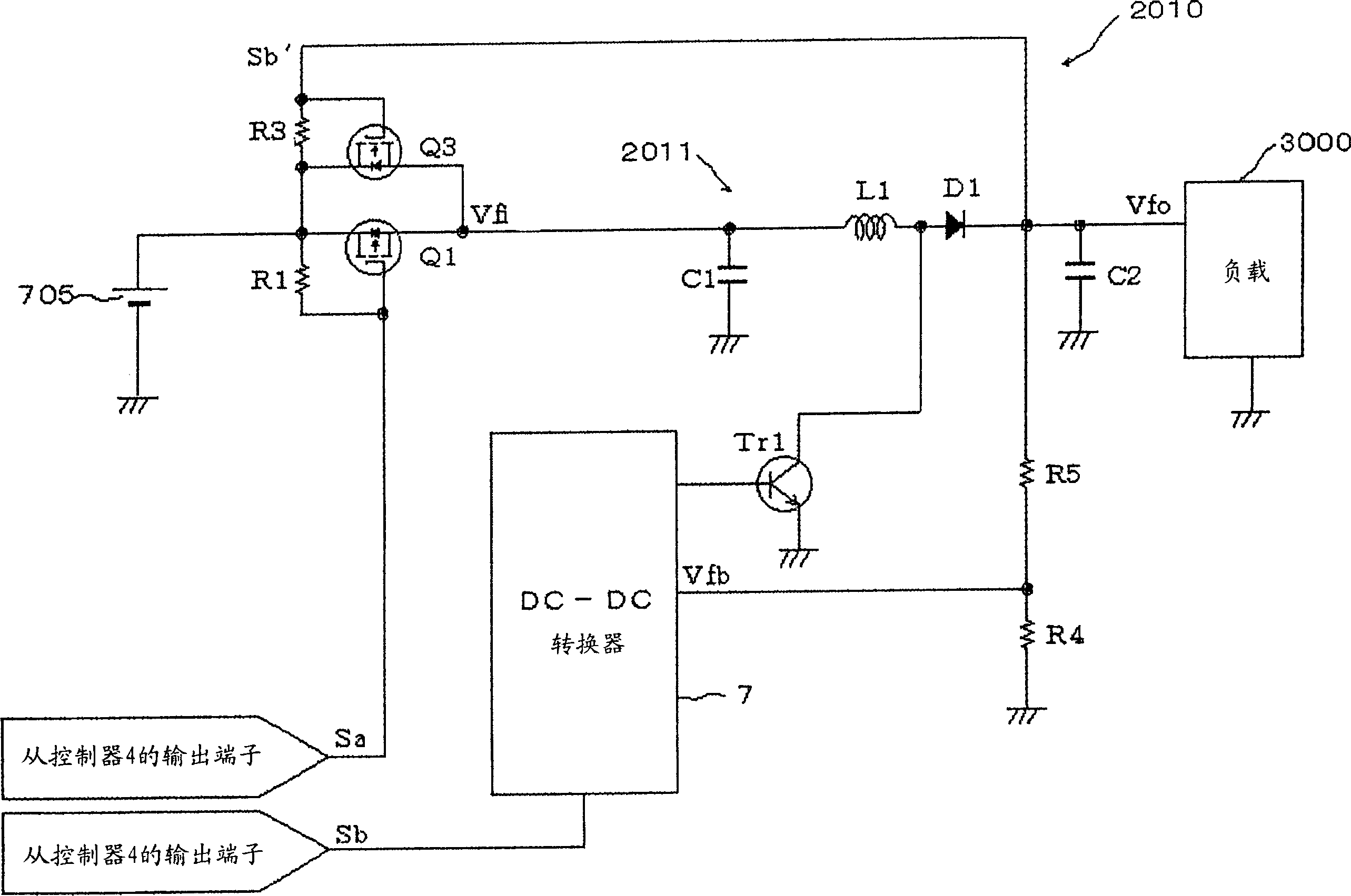
[0073] image 3 as well as Figure 4 It is a figure showing the second embodiment of the power switch circuit of the present invention, image 3 It is a circuit configuration diagram of main parts of a power switch circuit 2010 of a digital camera to which the second embodiment of the power switch circuit of the present invention is applied.

[0074] In addition, this embodiment is applicable to the same digital camera and power switch circuit 2000 as the digital camera 1 of the above-mentioned first embodiment. A detailed description thereof will be omitted, and the symbols used in the description of the first embodiment will be used as they are for descriptions of parts not shown in the drawings as needed.

[0075] exist image 3 In the power switch circuit 2010, between the battery voltage source 705 and the load 3000, the same p-channel MOSFETQ1 with a large on-resistance and an n-channel MOSFETQ3 with a small on-resistance are connected in parallel between the battery ...

Embodiment 3

[0096] Figure 5 It is a circuit configuration diagram of main parts of a power switch circuit 2020 of a digital camera to which the third embodiment of the power switch circuit of the present invention is applied.

[0097] In addition, this embodiment is applied to a digital camera similar to the digital camera 1 of the above-mentioned first embodiment, and is also applied to a power switch circuit similar to the power switch circuit 2010 of the above-mentioned second embodiment. In the description of this embodiment, , for the same structural parts as those of the above-mentioned first embodiment or second embodiment, the same symbols are assigned and detailed descriptions thereof are omitted, and for parts not shown, the same reference numerals used in the description of the first embodiment are used as they are necessary. Symbols are explained.

[0098] exist Figure 5 In the power switch circuit 2020, between the battery voltage source 705 and the load 3000, the above-m...


PUM


Abstract

The invention relates to a power switch circuit (2000), wherein when the power supply is connected, first connecting the MOSFET (Q1) with large conductive resistance; after preset time, connecting MOSFET (Q2) with lower conductive resistance; therefore, the invention can use simple structure to restrain the impact current when connecting the power supply. And the invention can be used in battery power supply.

Description

technical field [0001] The present invention relates to a power switch circuit. Specifically, it relates to a power switch circuit that is also compatible with battery power sources and the like, and that is inexpensive and appropriately prevents inrush current. Background technique [0002] As a power switch circuit of equipment, conventionally, when a large current flows, a transistor needs to flow an excessive base current, so the efficiency is lowered, and if a relay is used, mechanical reliability becomes a problem. [0003] Therefore, in recent years, power MOSFETs (Field Effect Transistors: Field Effect Transistors) are often used. In this way, if a power MOSFET is used, the power MOSFET can be controlled at a low voltage, has low on-resistance, and high efficiency. [0004] However, since the on-resistance is low, conversely, when the capacitance of the capacitor on the load side is large, the MOS switch is turned on, and as a result, a large inrush current flows. ...

Claims


Application Information

Patent Timeline
Patent Type & Authority Applications(China)
IPC IPC(8): H02H9/02H02J7/00G05F1/10H02M3/00
Inventor 青木一雅
Owner RICOH KK
Why Eureka
Try Eureka